


Return to Section TOC Return to Section TOC Return to Section TOC Return to Section TOC
Return to Master TOC Return to Master TOC Return to Master TOC Return to Master TOC
E-2
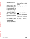
CONTROL CIRCUIT
OPERATION
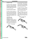
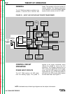
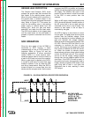
POWER INPUT CIRCUITS
The LN-7 GMA receives 115 VAC power
from the welding supply. This power is
applied to the trigger transformer which
reduces the voltage for use by the LN-7
electronics. The voltages produced are 24
VAC, used by the electronics and the trigger
circuit, and 8.8, VAC used by the optional
digital meter kit. The 115 VAC input power is
also sent to the SCR circuitry which powers
the wire feed motor. See Figure E.1.
THEORY OF OPERATION
LN-7 GMA WIRE FEEDER
FIGURE E.1 – INPUT LINE VOLTAGE AND TRIGGER TRANSFORMER.
TRIGGER
TRANS-
FORMER
24 VAC
8.8 VAC
115 VAC
115 VAC
CIRCUIT
BREAKER
OPTIONAL
METER KIT
OPTIONAL
TIMER OR
BURNBACK KIT
GROUND
LEAD
PROTECTOR
WIRE
SPEED
CONTROL
CR1
CONTROL
RELAY
CONTROL
BOARD
WIRE DRIVE
MOTOR
5-95 VDC
GUN
TRIGGER
SCR
POWER
CIRCUIT
FROM
WELDING
POWER
SUPPLY
DIODE
RECTIFIER
NETWORK
115 VAC
GAS
SOLENOID
TO WELDING
CONTACTOR
CURRENT
LIMITING
CIRCUIT
24 VDC
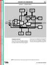
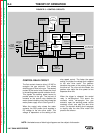
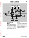
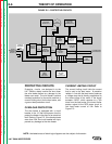
NOTE: Unshaded areas of block logic diagrams are the subject of discussion.
GENERAL
The LN-7 GMA wire feeder is available in two
versions, a two-roll and a four-roll wire
feeder. The operation of the two versions is
virtually identical. The following description
of the operation of the wire feeders applies
equally to both versions of the LN-7 GMA.