


Return to Section TOC Return to Section TOC Return to Section TOC Return to Section TOC
Return to Master TOC Return to Master TOC Return to Master TOC Return to Master TOC
TROUBLESHOOTING AND REPAIR F-31
LN-7 GMA WIRE FEEDER
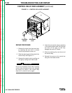
9. Pry the retaining clip from the control
relay. Remove the control relay from
the control PC board.
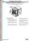
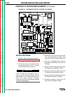
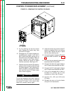
10. Disengage the PC board supports by
squeezing each support in turn with a
pair of pliers and gently pulling out on
the board next to the support. When all
seven supports have been discon-
nected, remove the control PC board
from the control box. See Figure F.9.
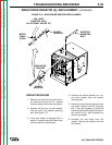
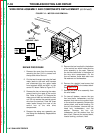
11. Prepare to mount the new PC board by
lining up all the mounting holes with the
PC board supports. Then, press the PC
board into place on the supports. Make
sure that the control PC board snaps
onto all seven supports.
Do not use excessive force when inserting
control relay. Excessive force can damage
the control PC board. If the control relay
does not fit, remove it and try again.
12. Install the control relay onto the new PC
board by pressing firmly and rocking
side to side. Secure the relay in place
with the relay retaining clip.
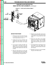
13. Connect the meter kit wires to PC board
terminals #508 and #509. See Figure
F.8.
14. Connect the gas solenoid wires to PC
board terminals #7 and #32A.
15. Connect the feed wire motor leads to
the PC board terminals #539 and #541.
16. Connect the GLP reed switch wires to
the PC board terminals #526 and #527.
17. If the unit is equipped with a timer or
burnback kit, connect the kit wire
connector to J104 on the PC board.
18. Connect J101, J102, and J103 to the
PC board.
19. Reinstall the cover on the wire feeder
using four hex head screws.
CONTROL PC BOARD REPLACEMENT
(continued)
FIGURE F.9 – REMOVING THE CONTROL PC BOARD.
CONTROL
PC BOARD
CAUTION