


Return to Section TOC Return to Section TOC Return to Section TOC Return to Section TOC
Return to Master TOC Return to Master TOC Return to Master TOC Return to Master TOC
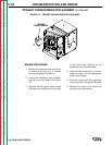
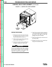
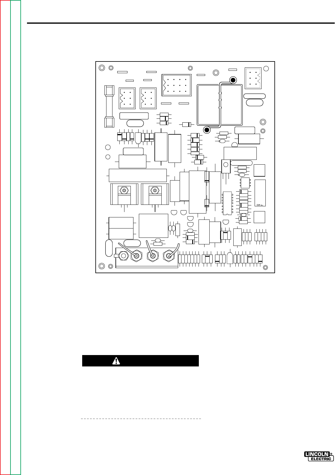
LN-7 GMA CONTROL
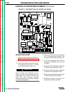
32A 7
508 509
539 541
526
527
J101
J103
J104
J102
1 2 3 4 5 6 7 8
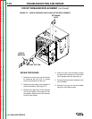
FIGURE F.8 – DISCONNECTING THE CONTROL PC BOARD.
CONTROL PC BOARD REPLACEMENT
(continued)
LN-7 GMA WIRE FEEDER
TROUBLESHOOTING AND REPAIRF-30
REPAIR PROCEDURE
1. Observe static precautions detailed in
PC Board Troubleshooting Procedures
at the beginning of this section.
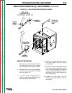
2. Remove the cover from the control box
by removing the four 5/16 in. screws
from the top and side of the unit.
Label all wires and connectors prior to
removal. All wires and connectors must be
reconnected to the same terminals from
which they were removed. Improper
connection may lead to component damage
or machine misoperation.
3. Disconnect J102, input cable connector
J101, and transformer connector J103
from the PC board. Refer to Figure F.8.
4. If the unit is equipped with a timer or
burnback kit, disconnect J104 From the
PC board.
5. Disconnect GLP reed switch wires from
PC board terminals #526 and #527.
6. Disconnect feed wire motor leads from
PC board terminals #539 and #541.
7. Disconnect the gas solenoid wires from
PC board terminals #7 and #32A.
8. Disconnect meter kit wires from PC
board terminals #508 and #509.
CAUTION