


Return to Section TOC Return to Section TOC Return to Section TOC Return to Section TOC
Return to Master TOC Return to Master TOC Return to Master TOC Return to Master TOC
LN-7 GMA WIRE FEEDER
THEORY OF OPERATION E-7
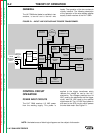
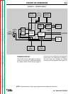
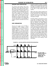
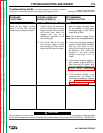
FIGURE E.6 – SILICON-CONTROLLED RECTIFIER OPERATION.
INPUT
CATHODE
GATE
GATE
OUTPUT
ANODE
AS THE GATE
PULSE IS APPLIED
LATER IN THE
CYCLE THE SCR
OUTPUT IS
DECREASED.
NOTE:
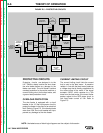
GROUND LEAD PROTECTION
The Ground Lead Protector (GLP) circuit
protects the ground lead that connects the
wire feeder to the welding power source.
When the circuit detects any current flow in
the ground lead, a contact closes in the
control circuit which de-energizes the control
relay. Refer to Figure E.5. This opens the
circuit for the welding relay in the welding
power supply to remove power from the
welding gun, shuts the gas and water
solenoids, and stops the wire feed motor.
The GLP circuit remains in this tripped state
until the reset button on the wire feeder is
pressed, or power is removed from the wire
feeder.
SCR OPERATION
Since the wire speed of the LN-7GMA is
controlled by SCR circuitry, a basic
understanding of how an SCR functions is
important. Refer to Figure E.6 and the
following explanation. A silicon controlled
rectifier (SCR) is a three terminal semi-
conductor device used to control currents to
a load. An SCR acts very much like a switch.
When a gate signal is applied to the SCR it
is turned on and there is current flow from
anode to cathode. In the on state the SCR
acts like a closed switch. When the SCR is
turned off there is no current flow, thus the
device acts like an open switch. As the name
suggests, the SCR is a rectifier, so it passes
current only during positive half cycles of the
AC supply, The positive half cycle is the
portion of the sine wave in which the anode
of the SCR is more positive than the
cathode.
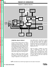
When an AC supply voltage is applied to the
SCR, the device spends a certain portion of
the AC cycle time in the on state and the
remainder of the time in the off state. The
amount of time spent in the on state is
controlled by the gate.
An SCR is fired by a short burst of current
into the gate. This gate pulse must be more
positive than the cathode voltage. Since
there is a standard pn junction between the
gate and cathode, the voltage between
these terminals must be slightly greater than
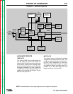
0.6 VDC. Once the SCR has fired it is not
necessary to continue the flow of gate
current. As long as current continues to flow
from anode to cathode the SCR will remain
on. When the anode to cathode current
drops below a minimum value, called holding
current, the SCR will shut off. This normally
occurs as the AC supply voltage passes
through zero into the negative portion of the
sine wave. If the SCR is turned on early in
the positive half cycle, the conduction time is
longer, resulting in greater SCR output. If the
gate firing time is later in the cycle the
conduction time is less, resulting in lower
SCR output.