


Return to Section TOC Return to Section TOC Return to Section TOC Return to Section TOC
Return to Master TOC Return to Master TOC Return to Master TOC Return to Master TOC
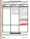
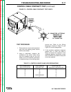
CONTROL RELAY TEST
(continued)
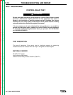
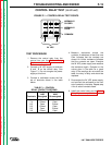
FIGURE F.1 – CONTROL RELAY TEST POINTS.
TEST PROCEDURE
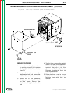
1. Remove the control relay from the
control box per the Control Relay
Replacement procedure.
2. Connect a 24 VDC supply to terminals
A and B on the control relay. See
Figure F.1. Do not energize the power
supply at this time.
3. Connect a multimeter across the first
set of terminals shown in the table
below.
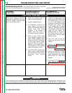
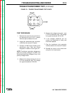
TABLE F.1 – CONTROL
RELAY CONTACT POSITIONS.
Terminals Terminals
A&B A&B
Terminals Energized De-energized
7-1 Open Closed
7-4 Closed Open
8-2 Open Closed
8-5 Closed Open
9-3 Open Closed
9-6 Closed Open
4. Measure resistance across the
contacts. A resistance of less than one
Ohm indicates that the contacts are
closed. An infinite resistance indicates
that the contacts are open. Energize
the 24 VDC power supply and measure
the resistance again. Compare to the
values given in the table for a good
relay. If the readings do not match the
table, the relay is faulty and should be
replaced.
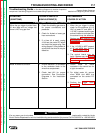
5. De-energize the 24 VDC power supply
and connect the multimeter to the next
set of contacts in the table. Repeat step
4 for all sets of contacts listed.
6. Install the control relay per the Control
Relay Replacement procedure.
TROUBLESHOOTING AND REPAIR F-13
LN-7 GMA WIRE FEEDER
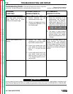
+
–
NORMALLY
CLOSED
NORMALLY
OPEN
COMMON
24 VDC