


OM-196 188 Page 12
SECTION 3 – INSTALLATION
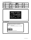
3-1. Specifications
Input
Rated Welding
Voltage
Wire Feed Speed
Wire
Maximum
Open-
Amperes Input
At Rated Load
Input
Power
Rated Welding
Output
Voltage
Range
Wire Feed Speed
Range*
Wire
Diameter
Range
Maximum
Open-
Circuit
Amperes Input
At Rated Load
Output 60 Hz,
KVA KW
Power
Output
Range
Range*
Diameter
Range
Circuit
Voltage DC
Output 60 Hz,
Three-Phase
KVA
KW
450 A @ 38 Volts DC,
Standard:
Three
Phase
450 A @ 38 Volts DC,
100% Duty Cycle;
565 A @ 43 Volts DC,
10 – 38
Standard:
50 To 780 ipm
.030 To .062 in
(0.8 To 1.6 mm)
95
31
21.6
19.4
Three
Phase
100% Duty Cycle;
565 A @ 43 Volts DC
,
60% Duty Cycle
10 – 38
50 To 780 ipm
(1.3 To 19.8 mpm)
.030 To .062 in
(0.8 To 1.6 mm
)
95
31
21.6
19.4
Phase
565 A @ 43 Volts DC,
60% Duty Cycle
(1.3 To 19.8 mpm)
(0.8 To 1.6 mm)
*Wire feed speed ranges are for GMAW welding. While pulse welding, wire feed speed ranges may be more limited (see Section 9)
**While idling
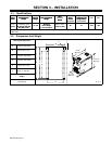
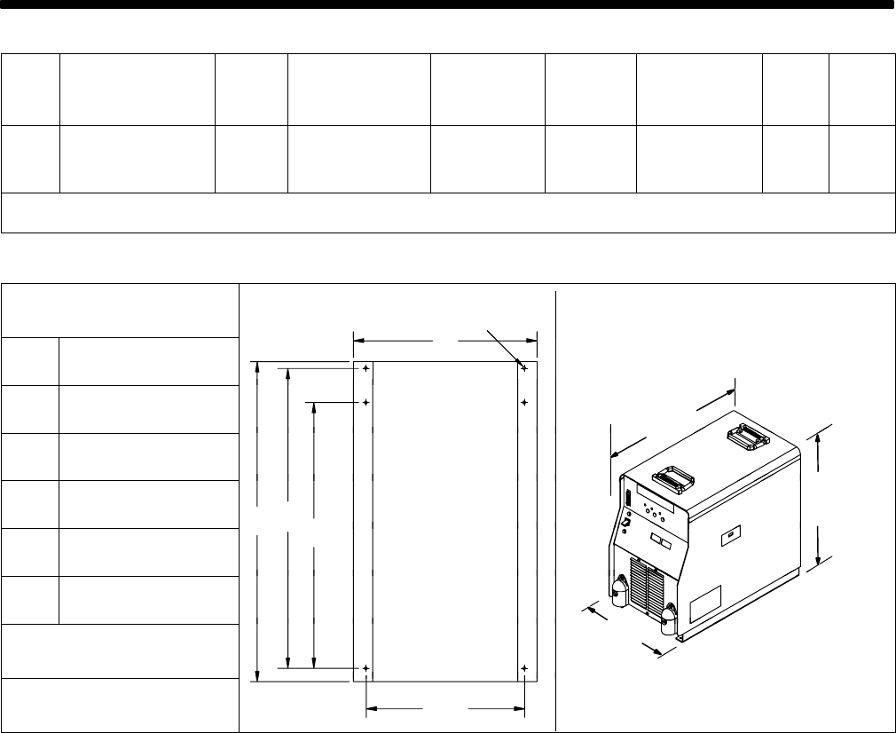
3-2. Dimensions And Weight
Hole Layout Dimensions
A
F
A 14-21/64 in (363.9 mm)
A
B 20-3/4 in (527.1 mm)
26 in
(660 mm)
C 23-27/64 in (594.9 mm)
(660 mm)
D 24-31/32 in (634.2 mm)
B
C
D
23-3/4 in
(603 mm)
E 12-3/8 in (314.3 mm)
B
C
D
F 9/32 in (7.1 mm) Dia.
14-1/2 in
Weight
14-1/2 in
(368 mm)
130 lb (59 kg)
E
801 914-A