


OM-196 188 Page 90
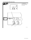
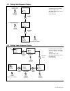
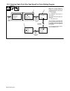
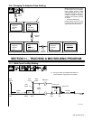
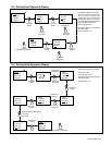
9-5. Setting Postflow Sequence Display
1 Postflow Parameters Display
Postflow can be adjusted from
0-9.9 seconds. If value set is zero
(0), there is no Postflow sequence.
1
> Poflw
0.0 Sec
Poflw
> 0.0 Sec
> Poflw
1.2 Sec
Parameter
Select
Parameter
Select
Set Desired Time
Increase/
Decrease
Increase
Proceed to next Section.
SECTION 10 – TEACHING A PULSE WELDING PROGRAM
See GMAW-P (Pulsed MIG) Process Guide supplied with unit for more
information.
NOTE
Ref. S-0259
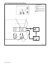
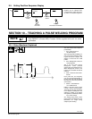
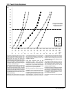
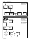
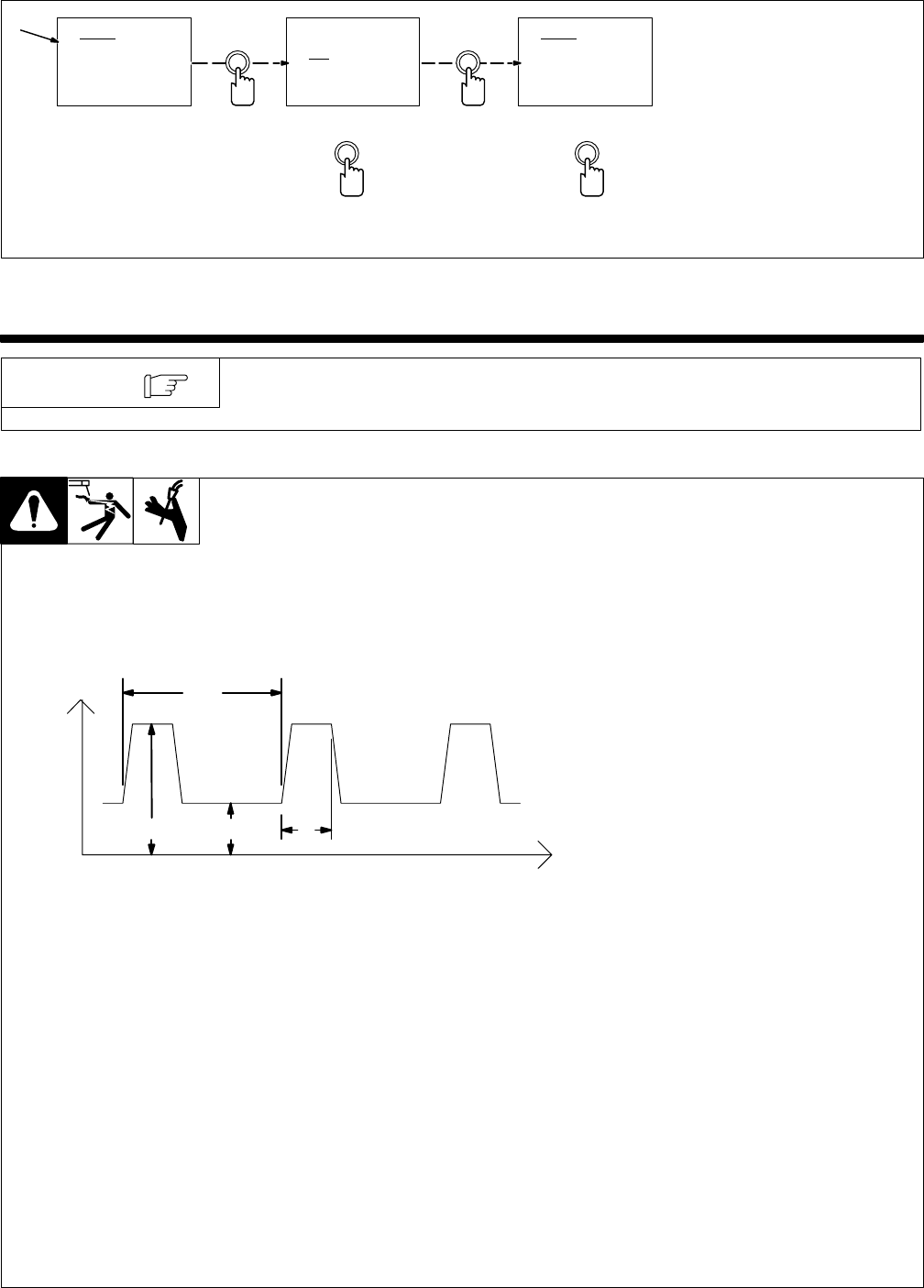
10-1. Pulse Waveform Explained
This unit controls weld output for
pulsed welds.
1 Apk – Peak Current Of
100-600 Amperes
Apk is the high pulse of welding cur-
rent. Peak current melts the weld-
ing wire and forms a droplet. The
droplet is forced into the weld
puddle.
2 Abk – Background Current Of
10-255 Amperes
Abk is the low weld current.
Background current preheats
welding wire and maintains the arc.
When background current is too
low, the arc is unstable and hard to
maintain.
3 PPS – Pulses Per Second Of
20-400
PPS, pulse rate, and frequency
(Hz) are used interchangeably. A
PPS or pulse rate of 60 Hz means
60 pulses of current are produced
each second.
4 PWms – Pulse Width Of
1.0-5.0 Milliseconds
PWms is the time spent at peak
current (1.2 ms is .0012 seconds).
This time must be long enough to
form a droplet of welding wire. The
stiffness or fluidity of the molten
weld puddle is controlled by PWms.
Vpk = Peak Voltage
Arc Voltage during peak current
phase of the pulse waveform. This
determines arc length during
adaptive pulse welding.
3
2 41
Time
Amps
(Current)