


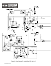
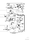

OM-196 188 Page 32
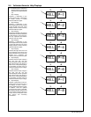
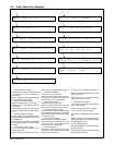
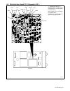
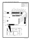
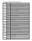
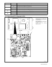
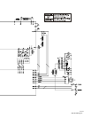
5-9. Diagnostic LED’s On Customer Interface Board PC14
LED Status Diagnosis
1
On Indicates –15 volts dc RA supply is present on customer interface board PC14.
1
Off Indicates –15 volts dc RA supply is not present on customer interface board PC14.
2
On Indicates +15 volts dc RA supply is present on customer interface board PC14.
2
Off Indicates +15 volts dc RA supply is not present on customer interface board PC14.
3
On Input signal On from robot for no Emergency Stop.
3
Off Input signal Off from robot for Emergency Stop.
4
On Indicates +24 volts dc RD supply is present on customer interface board PC14.
4
Off Indicates +24 volts dc RD supply is not present on customer interface board PC14.
5 On Input signal On from robot for shielding gas.
Off Input signal Off from robot for no shielding gas.
6 On Input signal On from robot to energize contactor.
Off Input signal Off from robot to not energize contactor.
7 On Input signal On from robot for jog retract.
Off Input signal Off from robot for no jog retract.
8
On Input signal On from robot for jog advance.
8
Off Input signal Off from robot for no jog advance.
9
On Indicates automatic configuration Bit D is set.
9
Off Indicates automatic configuration Bit D is not set.
10
On Input signal On for RPS-C.
10
Off Input signal Off for RPS-C.
11
On Input signal On for RPS-B.
11
Off Input signal Off for RPS-B.
12 On Indicates remote program A selected.
Off Indicates remote program A not selected.
13 On Input signal On from peripheral for touch sensor.
Off Input signal Off from peripheral for no touch sensor.
14
On Indicates automatic configuration Bit B is set.
14
Off Indicates automatic configuration Bit B is not set.
15
On Indicates automatic configuration Bit A is set.
15
Off Indicates automatic configuration Bit A is not set.
16
On Indicates automatic configuration Bit C is set.
16
Off Indicates automatic configuration Bit C is not set.
17
On Input signal On from relay CR4 for wire stuck in weld joint.
17
Off Input signal Off from relay CR4 for wire not stuck in weld joint.
18
On Input signal On from relay CR6 for flow (shielding gas or coolant) present.
18
Off Input signal Off from relay CR6 for flow (shielding gas or coolant) not present.
19
On Input signal On from relay CR5 for arc detect.
19
Off Input signal Off from relay CR5 for no arc detect.
20 On Input signal On from relay CR2.
Off Input signal Off from relay CR2.
On Input signal On from relay CR1 for welding power source ready and no detected errors present.
21
Off Input signal Off from relay CR1 for welding power source not ready, detected errors are present, or unit
is in Setup or Control mode.
22 On Input signal On from peripheral for flow switch.
Off Input signal Off from peripheral for no flow switch.