


OM-196 188 Page 14
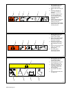
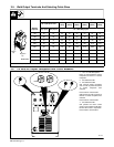
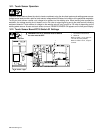
3-5. Weld Output Terminals And Selecting Cable Sizes
Total Cable (Copper) Length In Weld Circuit Not Exceeding
30 m (100 ft) Or Less
45 m
(150 ft)
60 m
(200 ft)
70 m
(250 ft)
90 m
(300 ft)
105 m
(350 ft)
120 m
(400 ft)
Welding
Amperes
10 – 60%
Duty Cycle
60 – 100%
Duty Cycle
10 – 100% Duty Cycle
100 25 25 25 35 35 50 55 55
150 35 35 35 50 55 70 95 95
200 35 35 50 55 70 95 120 120
250 35 50 55 70 95 120 2-70 2-70
300 50 55 70 95 120 2-70 2-95 2-95
Positive
(+)
350 55 70 95 120 2-70 2-95 2-95 2-120
Positive
(+)
Negative
(–)
400 55 70 95 120 2-70 2-95 2-120 2-120
Ref. 801 914-A
Negative
(–)
500 70 95 120 2-70 2-95 2-120 3-95 3-95
Ref. 801 914-A
600 95 120 2-70 2-95 2-120 3-95 3-120 3-120
*Weld cable size (mm
2
) is based on either a 4 volts or less drop or a current density of at least 300 circular mils per ampere. S-0007E
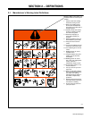
802 748
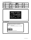
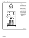
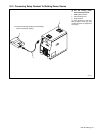
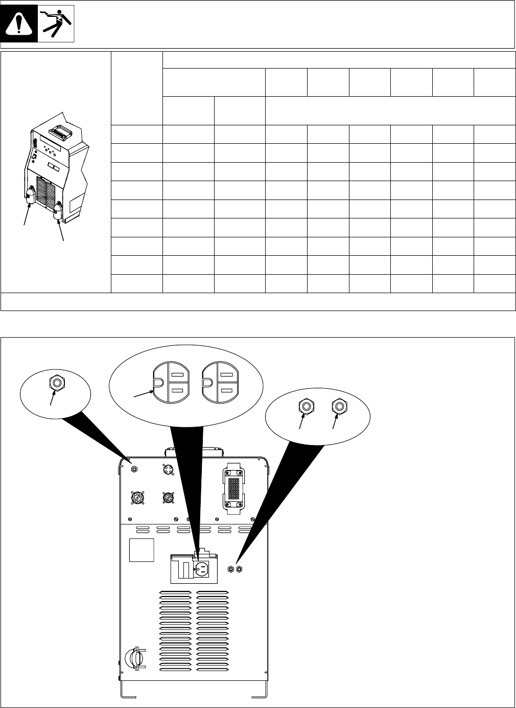
1 115 V 10 A AC Receptacle
Power is shared between duplex
receptacle and internal 14 socket
receptacle.
2 Circuit Breaker CB1
3 Circuit Breaker CB2
CB1 protects duplex receptacle
and 115 volts ac portion of internal
14 socket receptacle from
overload.
Press button to reset breaker.
CB2 protects 24 volts ac portion of
internal 14 socket receptacle from
overload.
Press button to reset breaker.
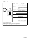
4 Circuit Breaker CB1
CB1 protects the motor control
circuitry from overload. If CB1 trips,
the wire drive motor is inoperative.
Press button to reset breaker.
2 3
1
3-6. 115 Volts AC Duplex Receptacle And Circuit Breakers
4