


OM-196 188 Page 31
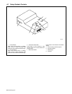
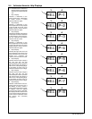
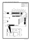
1 Customer Interface Board PC14
Diagnostic LED’s are visible inside
unit, located on PC14 (see illustration
for board location).
Refer to Section 5-9 for information
on diagnostic LED’s.
Reinstall top cover after checking
diagnostic LED’s.
1
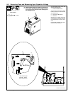
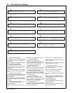
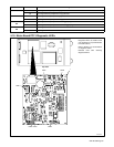
5-8. Customer Interface Board PC14 Diagnostic LED’s
LED1
LED6
LED3
LED2
LED4
LED5
Top View
LED7
LED8
LED10
LED12
LED9
LED11
LED14
LED13
LED15
LED16
LED23
LED25
LED22
LED24
LED21
LED20
LED19
LED18
LED17