


OM-196 188 Page 34
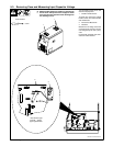
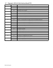
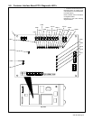
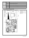
5-11. Diagnostic LED’s On Motor Board PC13
LED Status Diagnosis
1 On Indicates motor reverse relay is energized.
Red Off Indicates motor reverse relay is not energized.
2 On LED should be On. Indicates 115 volts ac input is sufficiently charging +170 volts dc bus for motor.
Red Off If LED is Off, check 115 volts ac input.
9 On LED should be On. Indicates +15 volts dc regulated bus is on.
Red Off If LED is Off, check for a short at board traces between bus and ground or at RC1-6 for 24 volts ac input
to regulator.
11 On LED should be On. Indicates +5 volts dc regulated bus is on.
Red
Off If LED is Off, check for a short at board traces between bus and ground or at RC1-6 for 24 volts ac input
to regulator.
4 On Indicates encoder input from motor to microprocessor is greater than 3 ipm.
Green Off Indicates motor is off or encoder input from motor to microprocessor is less than 3 ipm.
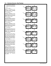
3 On Indicates microprocessor is operating without sensing any faults.
Green Blinking If microprocessor senses a fault, LED blinks to indicate type of fault.
3 Blinks PC13 sensed an overcurrent condition in wire drive. Check motor cables and connections for short cir-
cuits or bad connections. Check motor armature resistance, typical range is 10 to 20 ohms.
4 Blinks PC13 PWM (pulse width modulation) output was on, but no encoder pulses were sensed for more than
1 second. Check motor cables and connections for short circuits or bad connections. Electronic resetable
fuses called PTCs protect encoder power supply. If motor cable has a short circuit, PTCs will go to high
resistance to protect PC13. Do a pin-to-pin check for shorted conductors inside cable jacket, and replace
cable if necessary. Check motor encoder, and replace encoder if necessary.
5 Blinks Motor was not operating at proper speed for over 2 seconds. This fault results from monitoring amount of
velocity error (command speed – actual speed) to make sure that motor is running within a calculated per-
centage of command speed. For example, if motor is at a high speed and PWM is at maximum voltage,
a dirty liner or other load drags down motor speed will result in this fault condition. Clean liner, correct other
load conditions, such as spool hub tension too tight, or reduce wire feed speed.
6 Blinks +170 volts dc motor bus has dropped below +90 volts dc. Check 115 volts ac input to PC13.
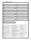
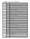
5-12. Troubleshooting
Trouble Remedy
No weld output; unit completely
inoperative.
Place line disconnect switch in On position (see Section 3-8).
Check and replace line fuse(s), if necessary, or reset circuit breaker (see Section 3-8).
Check for proper input power connections (see Section 3-8).
No weld output; meter display On. Check, repair, or replace remote control.
Unit overheated. Allow unit to cool with fan On (see Section 4-5).
Check voltmeter/ammeter Help displays.
Erratic or improper weld output. Use proper size and type of weld cable (see Section 3-5).
Clean and tighten all weld connections.
No 115 volts ac output at duplex
receptacle, Remote 14 receptacle.
Reset circuit breaker CB1 (see Section 3-6).
No 24 volts ac output at Remote 14 re-
ceptacle.
Reset circuit breaker CB2 (see Section 3-6).