


OM-196 188 Page 17
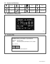
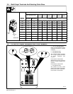
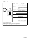
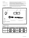
3-10. Peripheral Receptacle Functions
Function Socket Socket Information
Programmable
Output Relay Con-
A Contact closure to B dependent upon state of
programmed output (see Section 14-5). The closure
between A and B can carry a maximum of 0.6
amps at 125 VAC; or a maximum of 0.6 amps at
110 VDC.
AK
J
Output Relay Con-
tacts
B Contact closure to A dependent upon state of
programmed output (see Section 14-5). See socket
A information for current carrying capacity of
closure.
AK
B
M
J
C
C* Circuit common.
M
C
L
H
D
E
F
Purge
D Contact closure to C completes 24 volts dc
solenoid circuit to purge shielding gas line.
E
F
Coolant Flow
Switch Input
Signal
E Contact closure to F indicates coolant flow switch is
closed and recirculating coolant system is
operational.
Signal
F* Circuit common.
Jog + H** Contact closure to circuit common advances
welding wire at wire drive assembly.
802 748
Jog – J** Contact closure to circuit common retracts welding
wire at wire drive assembly.
K Contact closure to L energizes Touch Sensor
circuitry.
Touch Sensor ON
And Output Signal
L* Circuit common.
Touch Sensor ON
And Output Signa
l
M{ Part touched is selectable for either 0 volts dc
(common) or +24 volts dc (see Section 3-12).
Part touched +24 volts dc output signal referenced
to circuit common is factory default setting.
*Circuit common is same electrical reference point.
**Speed of Jog + and Jog – is at setup value for Jog IPM parameter.
{ Socket M can be changed to 0 volts dc (common) for part touched output signal (see Section 3-12).
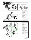
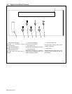
Note: A customer supplied matching amphenol plug [Miller Part No. 194 847 (Amphenol Part No. MS3106A20-33P and strain relief clamp
AN3057-12)] is required to use peripheral receptacle.