


OM-196 188 Page 13
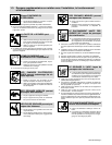
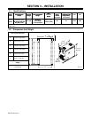
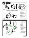
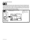
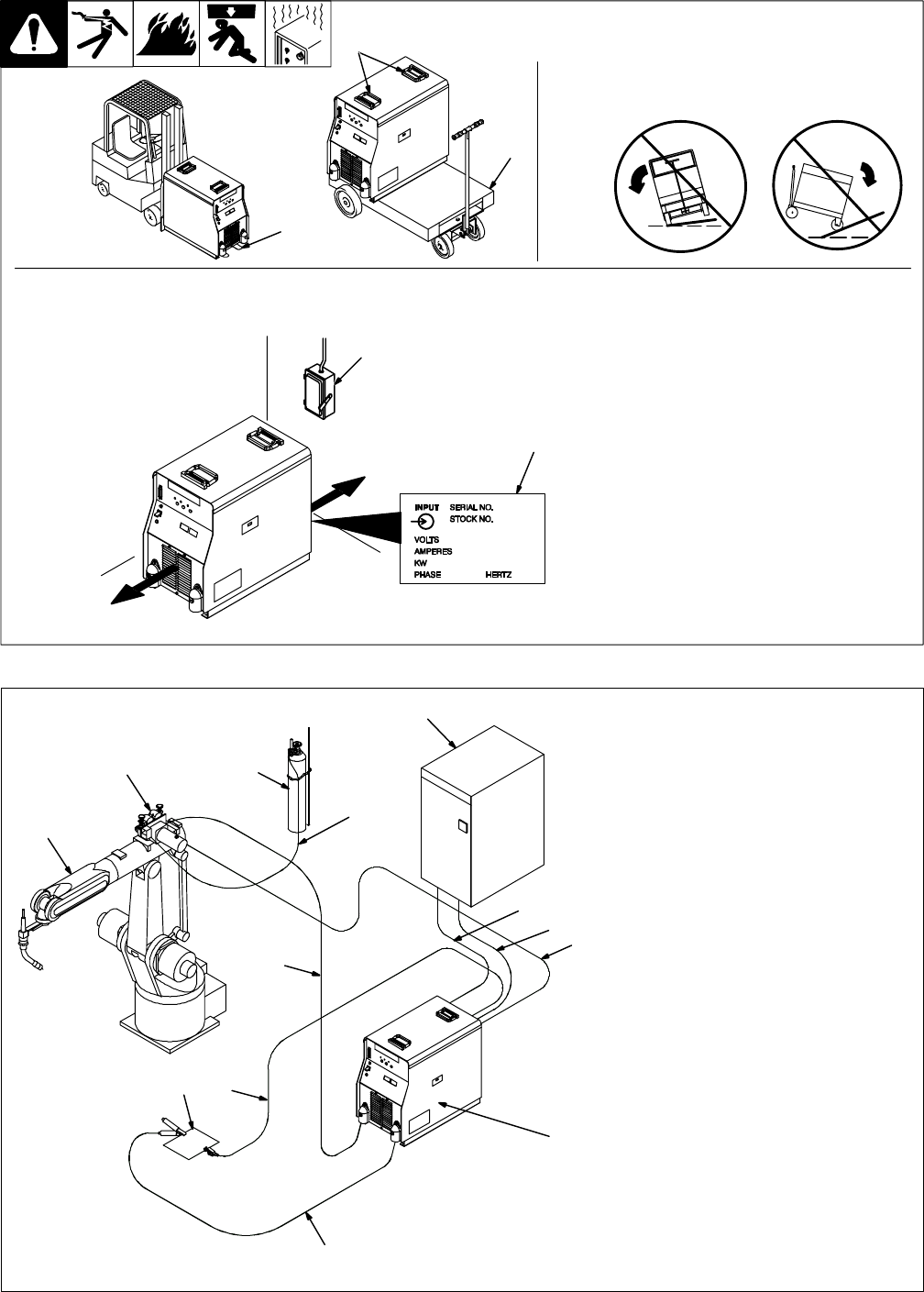
3-3. Selecting A Location
loc_2 3/96 - 801 958 / 801 914-A
1 Lifting Forks
Use lifting forks to move unit.
Extend forks beyond opposite side
of unit.
2 Lifting Handles
Use handles to lift unit.
3 Hand Cart
Use cart or similar device to move
unit.
4 Rating Label
Use rating label to determine input
power needs.
5 Line Disconnect Device
Locate unit near correct input
power supply.
Movement
2
3
Location
5
18 in
(460 mm)
18 in
(460 mm)
4
Y Do not move or operate
unit where it could tip.
Tipping
1
OR
Y Special installation may be required where gasoline or volatile
liquids are present – see NEC Article 511 or CEC Section 20.
801 915-B
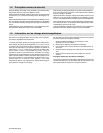
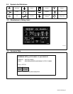
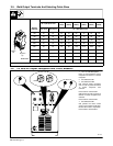
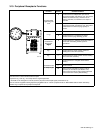
. The proper interface kit must
be installed in the interface unit
to allow it to be connected to the
robot.
1 Robot (Will Vary According To
Application)
2 Motor/Drive Assembly
3 Gas Cylinder
4 Gas Hose
5 Robot Control
6 Robot Input/Output Cable
7 Remote Program Select
Cable (Optional)
8 Gas And Motor Control Cable
9 Welding Power
Source/Interface Unit
10 Negative (–) Weld Cable
11 Workpiece
12 Voltage Sensing Lead
. Positive (+) voltage sensing
lead is contained in the motor
cable.
13 Positive (+) Weld Cable
1
2 3
4
5
8
6
7
9
10
11 12
13
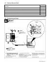
3-4. Connection Diagram