


OM-196 188 Page 15
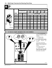
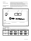
3-7. Electrical Service Guide
Three-Phase
Input Voltage 400
Input Amperes At Rated Output 31
Max Recommended Standard Fuse Or Circuit Breaker Rating In Amperes 45
Min Input Conductor Size In AWG/Kcmil 10
Max Recommended Input Conductor Length In Feet (Meters) 264 (80)
Min Grounding Conductor Size In AWG/Kcmil 10
Reference: 1993 National Electrical Code (NEC). S-0092J
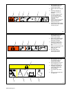
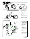
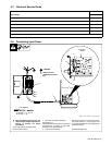
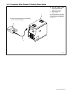
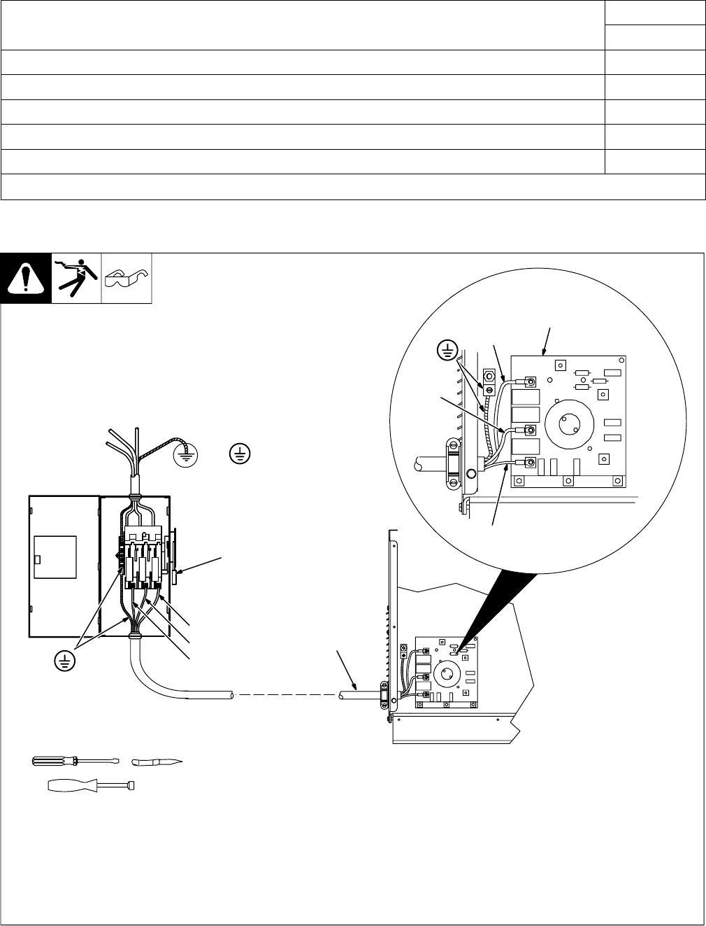
3-8. Connecting Input Power
ssb2.4* 1/94 – ST-801 718 / ST-801 946
Tools Needed:
5/16 in
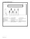
Input Filter
Board
L1
=GND/PE
Y Always connect
grounding conductor
first.
Y Turn Off welding power source, and
check voltage on input capacitors ac-
cording to Section 5-3 before
proceeding.
Check input voltage available at site.
Remove left side panel.
1 Input And Grounding Conductors
See Section 3-7.
Install ring terminals of proper size onto input
conductors for connection to input filter
board terminals (see illustration).
2 Line Disconnect Device
Select type and size of overcurrent protec-
tion using Section 3-7. Connect input and
grounding conductors to a deenergized line
disconnect device.
Reinstall left side panel.
L1
2
L2
L3
1
L2
L3