


OM-196 188 Page 20
SECTION 4 – OPERATION
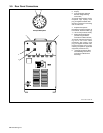
4-1. Operational Terms
The following is a list of terms and their definitions as they apply to this interface unit:
General Terms:
Adaptive Pulse Welding When the “adaptive pulse” welding process is selected, the unit will attempt to automatically regulate
pulse frequency in order to maintain a constant arc length, regardless of change in welding wire stick-
out.
Abk (Background Amperage) Abk is the low weld current. Background current preheats welding wire and maintains the arc. When
background current is too low, the arc is unstable and hard to maintain.
Apk (Peak Amperage) Apk is the high pulse of welding current. Peak current melts the welding wire and forms a droplet. The
droplet is forced into the weld puddle.
Vpk (Peak Voltage) Arc voltage during peak current phase of the pulse waveform. This determines arc length during
adaptive pulse welding.
Inductance In short circuit GMAW welding, an increase in inductance will decrease the number of short circuit
metal transfers per second (provided no other changes are made) and increase the arc-on time. The
increased arc-on time makes the pool more fluid.
PPS (Pulses Per Second) PPS, pulse rate, and frequency (Hz) are used interchangeably. A PPS or pulse rate of 60 Hz means
60 pulses of current are produced each second.
PWms (Pulse Width in Milliseconds) PWms is the time spent at peak current (1.2 ms is .0012 seconds). This time must be long enough to
form a droplet of welding wire. The stiffness or fluidity of the molten weld puddle is controlled by
PWms.
Synergic Synergic refers to the unit’s ability to use preprogrammed pulse parameters to determine the actual
pulse settings of Peak Amperage, Background Amperage, Pulse Frequency and Pulse Width at any
specific wire feed speed setting.
Trim Term used to represent arc length adjustments in pulse programs. Increasing trim increases the ac-
tual arc length. Likewise, decreasing trim shortens arc length. Trim is replaced by volts in MIG pro-
grams.
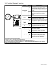
Setup Pendant Terms:
Card Mode Is used to select use of the optional data card storage and retrieval capabilities.
Process Mode Is used to select the type of process to be used, including Pulse, Adaptive Pulse, or Mig.
Sequence Mode Is used to select and program the weld sequences which include preflow, run-in, weld, crater,
burnback, and postflow.
Setup Screen Terms:
Access Code NOTE: The optional Data Card is required to activate this feature. With code off, access to the setup
displays is not restricted. With code on, the operator must know and enter the access code to access
or change any of the setup displays.
To use code, press Parameter Select button to enter access code. When the correct letter is entered,
the indicator automatically moves to the next character. When the final access code letter is entered,
the display automatically changes to the initial setup display.
Arc Start NOTE: Do not use the Hot Start setting for .035 in (9 mm) or smaller wire. Use the Hot Start mode for
pulse welding with 450 Ampere Inverter Model when high initial weld current is necessary to start
large diameter welding wires. When in Hot Start, the 450 Ampere Inverter Model starts the arc in the
CV mode and switches to CC once the arc is started. Do not use Hot Start unless using 450 Ampere
Inverter Model.
Arc Time Allows actual arc time up to 9,999.99 hours and weld cycles up to 999,999 to be accumulated and
displayed on the digital display, and can be reset to zero as required.
Mig Type (Voltage
Correction)
With DVC Voltage Correction On, the unit uses closed-loop control based on voltage feedback to
maintain set voltage parameters. With DVC Voltage Correction Off, feedback from the arc is not used
for closed-loop feedback to maintain voltage parameters. Feedback from the arc is still used for other
functions.
Name Feature When using the optional Data Card and turning the name feature on, programs written to the card can
be identified by name, number, job number, etc.
Program Reset By selecting program reset in the memory reset mode, the unit defaults to original factory program
settings for the program last active. All other program and setup information remains the same.
Range The interface requires that the voltage and amperage range of the welding power source be entered.
Obtain this information from the welding power source Owner’s Manual.
Security NOTE: The optional Data Card is required to activate this feature. Is used to limit what the operator
can control. This includes accessing the number of the program, 1 through 8, and the range of weld-
ing parameters within the program.
Software Screen Selection of this function will display the software version of the unit. When talking with factory service
personnel, this number may be required.