


Section 3
Receiving & Installation
Receiving & Installation 3–1MN735
Receiving & Inspection
Baldor Controls are thoroughly tested at the factory and carefully packaged
for shipment. When you receive your control, there are several things you
should do immediately.
1. Observe the condition of the shipping container and report any
damage immediately to the commercial carrier that delivered your
control.
2. Remove the control from the shipping container and remove all
packing materials. The container and packing materials may be
retained for future shipment.
3. Verify that the part number of the control you received is the same as
the part number listed on your purchase order.
4. Inspect the control for external physical damage that may have been
sustained during shipment and report any damage immediately to the
commercial carrier that delivered your control.
5. If the control is to be stored for several weeks before use, be sure that
it is stored in a location that conforms to published storage humidity
and temperature specifications stated in this manual.
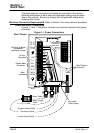
Location and Mounting
The location of the control is important. Installation should be in an area
that is protected from direct sunlight, corrosives, harmful gases or liquids,
dust, metallic particles, and vibration. Exposure to these can reduce the
operating life and degrade performance of the control.
Several other factors should be carefully evaluated when selecting a
location for installation:
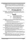
To maintain compliance with European Electrical Safety Standard
VDE0160(1994)/EN50178 (1998) the control must be mounted inside an
enclosure that requires a tool for opening. The enclosure should provide
15dB attenuation to radiated emissions between 30–100MHz.
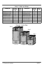
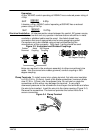
Mount the drive vertically on a solid, flat, non–flammable, vertical surface.
It can be panel–mounted, or rail–mounted on a rail complying with
EN50022 (35mm DIN). For DIN mount, hang the unit on the top DIN rail
and push the unit onto the bottom DIN rail until it snaps in to position.
Secure with a screw in the lower hole. See mounting drawing in Section 6
of this manual.
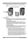
1. For effective cooling and maintenance, the control should be mounted
vertically on a smooth non-flammable surface.
2. At least 4.0 inches (100mm) top and bottom clearance must be
provided for air flow. At least 0.4 inches (10mm) clearance is required
between controls (each side).
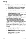
3. Operating Altitude derating. Up to 3300 feet (1000 meters) no
derating required. Derate the continuous and peak output current by
1% for each 330 feet (100 meters) above 3300 feet. Maximum
operating altitude 16,500 feet (5,000 meters).
4. Operating Temperature derating. 0°C to 40°C ambient. Linear
derating to 50°C maximum ambient.