


3–6 Receiving & Installation MN735
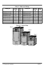
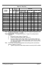
Table 3-2 Wire Size
Output
Current
Wire Size
Catalog
Number
Size
Cont. Peak
L1, L2, L3, N,
GND and Motor
DC+, DBR TH1A, TH1B
(Amps) (Amps)
AWG MM
2
AWG MM
2
AWG MM
2
ID35D8A1F5-CRH 1 1.5 2.3 12 2.5 12 2.5
ID35D8A2F2-CRH 1 2.2 3.3 12 2.5 12 2.5
ID35D8A03-CRH 1 3.0 4.5 12 2.5 12 2.5
ID35D8A04-CRH 1 4.0 6.0 12 2.5 12 2.5
ID35D8A07-CRH 2 7.0 10.5 12 2.5 12 2.5
ID35D2A10-CRH 3 10.5 15.8 10 2.5 10 2.5 12 2.5
ID35D2A16-CRH 3 16.5 24.8 10 2.5 10 2.5 12 2.5
ID35D4A1F5-CRH 2 1.5 2.3 12 2.5 12 2.5 12 2.5
ID35D4A02-CRH 2 2.0 3.0 12 2.5 12 2.5 12 2.5
ID35D4A2F5-CRH 2 2.5 3.8 12 2.5 12 2.5 12 2.5
ID35D4A4F5-CRH 2 4.5 6.8 12 2.5 12 2.5 12 2.5
ID35D4A5F5-CRH 2 5.5 8.3 12 2.5 12 2.5 12 2.5
ID35D4A09-CRH 3 9.0 13.5 10 2.5 10 2.5 12 2.5
ID35D4A12-CRH 3 12.0 18.0 10 2.5 10 2.5 12 2.5
ID35D4A16-CRH 3 16.0 24.0 10 2.5 10 2.5 12 2.5
Note: All wire sizes based on 75°C copper wire, 40°C ambient temperature, 4-6
conductors per conduit or raceway.
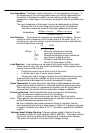
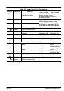
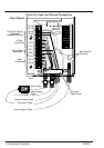
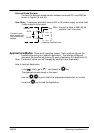
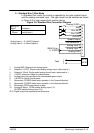
Power Connections The signals are shown in Figure 3-5 and described in
Table 3-3.
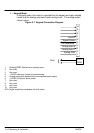
1. Remove the cover, shown in Figure 3-2.
2. Loosen the grounded cable clamp, Figure 3-5.
3. Connect the Mains Cable, Motor Cable, Dynamic Brake Cable and
Thermistor Cable wires, if used to their proper clamp terminal, Figure
3-5. Be sure the shields of all shielded cables are in contact with the
grounded cable clamp.
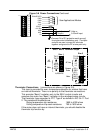
Note: This control must have two separate mains earth grounds connected as
shown in Figures 3-5 and 3-6.
4. Tighten the grounded cable clamp screws to securely hold the cables.