


Section 5
Troubleshooting
Troubleshooting 5–1MN735
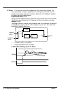
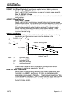
Trips The trip display message is briefly displayed repeatedly (flashing) on the
screen to warn of an imminent trip. Some trip conditions need time to take
effect. The warning can allow you time to resolve the situation. The
message will clear when you use the keypad, but after a short time will
reappear until the problem is resolved, or the drive trips.
When a trip occurs, the control’s power stage is immediately disabled
causing the motor and load to coast to a stop. The trip is latched until action
is taken to reset it. This ensures that trips due to transient conditions are
captured and the Inverter is disabled, even when the original cause of the
trip is no longer present. At this time, the activated alarm is displayed on
the keypad display.
Reset a Trip
All trips must be reset before the Inverter can be re–enabled. A trip can
only be reset once the trip condition is no longer active, i.e. a trip due to a
heatsink over–temperature will not reset until the temperature is below the
trip level. You can reset the trip as follows:
1. Press the
(STOP) key to reset the trip and clear the alarm from
the display.
2. Remove and then re–apply the RUN command and the drive will run
normally.
Success is indicated by either
or the Local Setpoint being displayed.
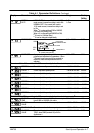
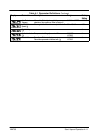
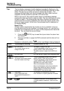
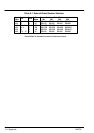
Display Trip Message and Meaning Possible Reason for Trip
DC LINK HIGH
The Inverter internal dc link
voltage is too high
The supply voltage is too high
Trying to decelerate a large inertia load too
quickly; DECEL TIME time too short
The brake resistor is open circuit (400V unit
only)
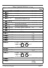
DC LINK LOW DC LINK low trip. Supply is too low/power down
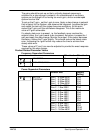
OVERCURRENT
The motor current being drawn
from the Inverter is too high
Trying to accelerate a large inertia load too
quickly; ACCEL TIME time too short
Trying to decelerate a large inertia load too
quickly; DECEL TIME time too short
Application of shock load to motor
Short circuit between motor phases
Short circuit between motor phase and earth
Motor output cables too long or too many
parallel motors connected to the Inverter
FIXED BOOST level set too high
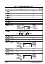
HEATSINK
OVERTEMPERATURE
Drive heatsink temperature >
100ºC
The ambient air temperature is too high
Poor ventilation or spacing between Inverters
A current of less than 1mA is present when
4–20mA setpoint is selected – look for a wire
break