


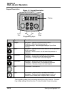
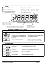
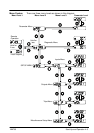
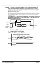

4–8 Start–Up and Operation MN735
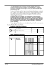
Table 4-1 Parameter Definitions Continued
Display Parameter Description Range Factory
Setting
Parameters
P
501 and
P
502 are visible in the PAR menu when Application 5 is selected in parameter
P
1
PI P GAIN The PID P"roportional gain 0.00 to 100.00 1.00
PI I GAIN The PID I"ntegral gain 0.00 to 100.00 0.00
PID D GAIN ~
The PID D"erivative gain 0.00 to 100.00 0.00
PID D FILTER
TC ~
A first order lag filter to help attenuate high
frequency noise on the derivative term. This
parameter determines the filter time constant.
0.05 to 10.00s 0.05s
PID FEEDBACK
GAIN ~
A multiplier applied to the PID feedback signal -10.00 to 10.00 1.00
PID LIMIT ~
Determines the maximum positive and negative
excursion (Limit) of the PID output
0.00 to 300.00% 0.00
PID SCALING
~
An overall scale factor which is applied after the
PID positive and negative limit clamps
-3.0000 to 3.0000 0.00
PID ERROR
~
Error=(Setpoint-Feedback) x (Feedback Gain) x.xx % x.xx %
PID OUTPUT
~
The output of the PID function block x.xx % x.xx %
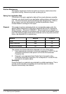
SET::IN Menu
DIN 1 INVERT True =Inverts the input signal. 0= False
1= True
0
DIN 2 INVERT True =Inverts the input signal. 0= False
1= True
0
DIN 3 INVERT True =Inverts the input signal. 0= False
1= True
0
DIN 4 INVERT True =Inverts the input signal. 0= False
1= True
0
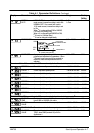
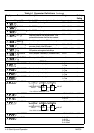
AIN 1 SCALE
VALUE
+
SCALE
OFFSET
X
INPUT
TYPE
UNPROCESSED
0 to 100% of selected TYPE
-150.0 to 150.0% 100.0%
AIN 1 OFFSET -100.0 to 100.0% 0.00%
AIN 1 TYPE 0= 0-10V
1= 0-5V
0
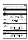
AIN 2 SCALE
VALUE
+
SCALE
OFFSET
X
INPUT
TYPE
UNPROCESSED
0 to 100% of selected TYPE
-150.0 to 150.0% 100.0%
AIN 2 OFFSET -100.0 to 100.0% 0.0%
AIN 2 TYPE 0= 0-10V
1= 0-5V
2= 0-20mA
3= 4-20mA
3