


Appendix A
Dynamic Brake
Appendix A–1MN735
230VAC 1 & 3 Phase Controls All controls are supplied without braking resistors.
Size 1 and 2 – 230VAC 1 Phase
Size 1 and 2 230VAC controls have no external dynamic brake capability.
Size 3 – 230VAC 3 Phase
Size 3 230VAC controls have internal brake circuit and can accept external
brake resistor.
460VAC 3 Phase Controls
Size 2 and 3 – 460VAC
Size 2 and 3 460VAC controls have internal brake circuit and can accept
external brake resistor. The dynamic brake circuit is designed for short term
stopping or braking only. It is not rated for a continuously overhauling load.
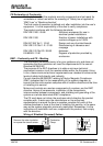
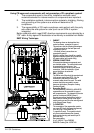
All controls are supplied without braking resistors. The dynamic brake
switch terminals allow easy connection of an external resistor. These
resistors should be mounted on a heatsink (enclosure panel) and covered
to prevent severe buring.
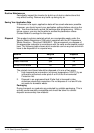
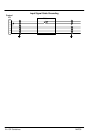
Brake Calculations
Brake assemblies must be rated to absorb the peak brake power during
deceleration and the average power over the complete cycle.
P
pk
+
0.0055 xJx(n
1
2
* n
2
2
)
t
b
(W)
P
av
+
P
pk
t
c
xt
b
where: J = total inertia (kgm
2
)
n
1
= initial speed (RPM)
n
2
= final speed (RPM)
t
b
= brake time (seconds)
t
c
= cycle time (seconds)
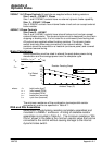
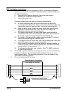
Resistor Derating Graph
0
20
40
60
80
100
120
0 25 50 75 100 125 150 175 200
Ambient Temp (C)
% of Rated
Power
chassis mounted
free air
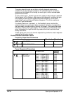
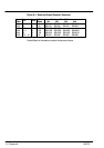
The minimum resistance of the combination (series/parallel resistor
connections) must be as specified in Table A-1.
RGA and RGJ Assemblies
Assemblies include braking resistors completely assembled and
mounted in a NEMA 1 enclosure. A listing of available resistor
assemblies is provided in Table A-1. The minimum resistance “Min
Ohms” shown in the table is the minimum resistor value that can be
connected to the control without causing damage to the internal
dynamic brake switch.