


3–8 Receiving & Installation MN735
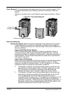
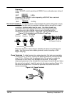
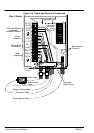
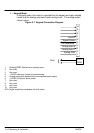
Figure 3-5 Power and Ground Connections
10
9
8
7
6
5
4
3
2
1
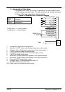
M2/V
M3/W
L1
TH1A
TH1B
L2/N
RL1A
RL1B
M1/U
DBR
L3
DC+
Dynamic Brake Cable
Mains Supply
Cable
Motor Cable
Thermistor Cable
Wire Retainer
(Channel)
Control Signal Cable
L1, L2, L3, GND
Size 2 Shown
Use 2 Ground
Wires
Grounded
Cable Clamp
Use a cable tie
in this area for
control wires.
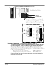
Motor
Connections
Dynamic Brake
Connections
AC Line
Connections
TH1A and TH1B must
be jumpered if
thermistor is not used