


Receiving & Installation 3–5MN735
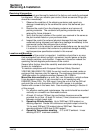
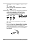
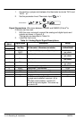
Examples:
A 5hp, 230VAC control operating at 208VAC has a reduced power rating of
4.5hp.
5HP
208VAC
230VAC
+ 4.5hp
Likewise, a 3hp, 460VAC control operating at 380VAC has a reduced
power rating of 2.47hp.
3HP
380VAC
460VAC
+ 2.47hp
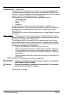
Electrical Installation All interconnection wires between the control, AC power source,
motor, host control and any operator interface stations should be in metal
conduits or shielded cable must be used. Use listed closed loop
connectors that are of appropriate size for wire gauge being used.
Connectors are to be installed using crimp tool specified by the
manufacturer of the connector. Only class 1 wiring should be used.
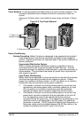
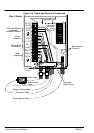
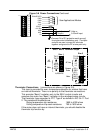
Figure 3-3 Unshielded and Shielded Couplings
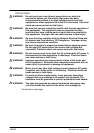
Holes are required in the enclosure assembly to allow connections to be
made. Use the correct size rubber grommet, conduit coupling or 360
degree coupling.
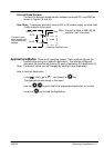
Rubber
Grommet
Metal
Coupling
360 Degree
Coupling
360 Degree Coupling
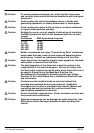
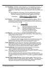
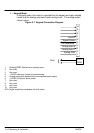
Clamp Terminals To install a wire into a clamp terminal, first strip wire insulation
to 0.20–0.24 in. (5–6mm). Insert a flat–blade screwdriver, maximum blade
size 0.138 in. (3.5mm) into the adjacent hole. Do not twist or rotate the
screwdriver as this action may damage the terminal. A very slight
downward pressure on the screwdriver should open the terminals and allow
the wire to be inserted. Insert the wire into the clamp opening (Figure 3-4).
Remove the screwdriver. The terminal provides the correct force for a
secure connection.
Figure 3-4 Clamp Terminal