


B–2 CE Guidelines MN735
Using CE approved components will not guarantee a CE compliant system!
1. The components used in the drive, installation methods used,
materials selected for interconnection of components are important.
2. The installation methods, interconnection materials, shielding, filtering
and grounding of the system as a whole will determine CE
compliance.
3. The responsibility of CE mark compliance rests entirely with the party
who offers the end system for sale (such as an OEM or system
integrator).
Baldor products which meet EMC directive requirements are indicated by a
“CE” mark. A duly signed CE declaration of conformity is available from Baldor.
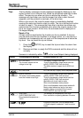
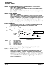
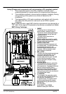
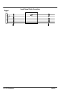
EMC Wiring Technique
1 CABINET
The drawing shows an electroplated zinc
coated enclosure, connected to ground.
This enclosure has the following advantages:
- All parts mounted on the back plane are
connected to ground.
- All shield (screen) connections are
connected to ground.
Within the cabinet there should be a spatial
separation between power wiring (motor and
AC power cables) and control wiring.
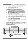
2 SCREEN CONNECTIONS
All connections between components must
use shielded cables. The cable shields must
be connected to the enclosure. Use
conductive clamps to ensure good ground
connection. With this technique, a good
ground shield can be achieved.
3 EMC - FILTER
The EMI or main filter should be mounted next
to the power supply (here BPS). For the
connection to and from the main filter
screened cables should be used. The cable
screens should be connected to screen
clamps on both sides. (Exception: Analog
Command Signal).
4 Grounding (Earth)
For safety reasons (VDE0160), all BALDOR
components must be connected to ground
with a separate wire. The diameter of the wire
must be at minimum AWG#6 (10mm@).
Ground connections (dashed lines) must be
made from the central ground to the regen
resistor enclosure and from the central ground
to the Shared Power Supply.
5 Y-CAPACITOR
The connection of the regeneration resistor
can cause RFI (radio frequency interference)
to be very high. To minimize RFI, a
Y-capacitor is used. The capacitor should
only be connected between the dynamic
brake resistor housing and terminal pin R1
(lead from Lin).
Recommendation:
0,1µF / 250VAC Type: PME265
BALDOR-Ordering-No.: ASR27104
Y
Capacitor