


CE Guidelines B–3MN735
EMC Installation Instructions
To ensure electromagnetic compatibility (EMC), the following installation
instructions should be completed. These steps help to reduce interference.
Consider the following:
• Grounding of all system elements to a central ground point
• Shielding of all cables and signal wires
• Filtering of power lines
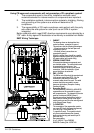
A proper enclosure should have the following characteristics:
A) All metal conducting parts of the enclosure must be electrically
connected to the back plane. These connections should be made with
a grounding strap from each element to a central grounding point .
B) Keep the power wiring (motor and power cable) and control wiring
separated. If these wires must cross, be sure they cross at 90
degrees to minimize noise due to induction.
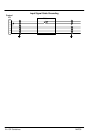
C) The shield connections of the signal and power cables should be
connected to the screen rails or clamps. The screen rails or clamps
should be conductive clamps fastened to the cabinet.
D) The cable to the regeneration resistor must be shielded. The shield
must be connected to ground at both ends.
E) The location of the AC mains filter has to be situated close to the drive
so the AC power wires are as short as possible.
F) Wires inside the enclosure should be placed as close as possible to
conducting metal, cabinet walls and plates. It is advised to terminate
unused wires to chassis ground.
G) To reduce ground current, use at least a 10mm
2
(6 AWG) solid wire
for ground connections.
Grounding in general describes all metal parts which can be connected to a
protective conductor, e.g. housing of cabinet, motor housing, etc. to a
central ground point. This central ground point is then connected to the
main plant (or building) ground.
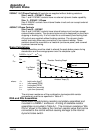
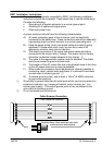
Or run as twisted pair at minimum.
Cable Screens Grounding
Cable (Twisted Pair Conductors)
Conductive Clamp - Must contact bare cable shield
and be secured to metal backplane.