


3–4 Receiving & Installation MN735
Line Impedance The Baldor control requires a 1% line impedance minimum . If
the impedance of the incoming power does not meet the requirement for
the control, a 3 phase line reactor can be used to provide the needed
impedance in most cases. Line reactors are optional and are available from
Baldor.
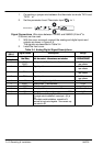
The input impedance of the power lines can be determined as follows:
Measure the line to line voltage at no load and at full rated load.
Use these measured values to calculate impedance as follows:
%Impedance +
(Volts
No Load Speed
* Volts
Full Load Speed
)
(Volts
No Load Speed
)
100
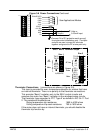
Line Reactors Three phase line reactors are available from Baldor. The line
reactor to order is based on the full load current of the motor (FLA). If
providing your own line reactor, use the following formula to calculate the
minimum inductance required.
L +
(V
L* L
0.03)
(I 3
Ǹ
377)
Where: L Minimum inductance in Henries.
V
L-L
Input volts measured line to line.
0.03 Desired percentage of input impedance.
I Input current rating of control.
377 Constant used with 60Hz power.
Use 314 if input power is 50Hz.
Load Reactors Line reactors may be used at the control output to the motor.
When used this way, they are called Load Reactors. Load reactors serve
several functions that include:
S Protect the control from a short circuit at the motor.
S Limit the rate of rise of motor surge currents.
S Slowing the rate of change of power the control delivers to the motor.
Load reactors should be installed as close to the control as possible.
Selection should be based on the motor nameplate FLA value.
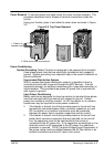
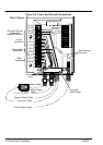
Power Disconnect A power disconnect should be installed between the input
power service and the control for a fail safe method to disconnect power.
The control will remain in a powered-up condition until all input power is
removed from the control and the internal bus voltage is depleted.
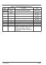
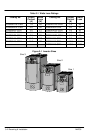
Protective Devices Recommended fuse sizes are based on the following:
115% of maximum continuous current for time delay.
150% of maximum continuous current for Fast or Very Fast action.
Note: These general size recommendations do not consider harmonic currents or
ambient temperatures greater than 40°C.
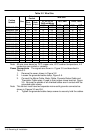
Be sure a suitable input power protection device is installed. Use the
recommended fuses and wire sizes shown in Table 3-2 is based on the use
of copper conductor wire rated at 75 °C. The table is specified for NEMA B
motors.
Reduced Input Voltage Derating All power ratings stated in Section 6 are for
the stated nominal AC input voltages (230 or 460VAC). The power rating of
the control must be reduced when operating at a reduced input voltage.
The amount of reduction is the ratio of the voltage change.