


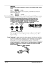

Receiving & Installation 3–9MN735
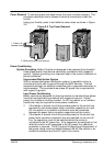
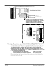
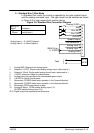
Figure 3-6 Power Connections Continued
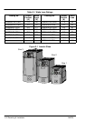
10
9
8
7
6
5
4
3
2
1
Feedback
Setpoint
10k Speed
Setpoint
Volts or
0–20mA Input
M1/U
M2/V
M3/W
L1
TH1A
TH1B
L2/N
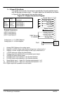
Size 1 and 3 Terminal Strips
L3
M2/V
M3/W
L1
L2
M1/U
DC+
DBR
DC–
TH1A
TH1B
Size 1
Size 3
Connect 0V to PE (protective earth ground)
for single control installations only. If multiple
controls are used, connect 0V terminals
together and ground to PE at one point only.
1φ 230VAC
3φ 460VAC
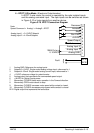
See Applications/Modes
Dynamic
Brake
Motor
AC Line
Motor
AC
Line
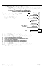
DIN4/DOUT2
DIN3
DIN2
DIN1
+24V
AOUT1
+10V Ref
AIN2
AIN1
0V
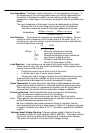
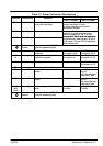
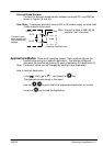
Thermistor Connections (connections are shown in Figure 3-5).
This input is provided for over–temperature detection for motors that have
an internal thermistor. There is no polarity to the thermistor connections.
This provides “Basic” insulation only to the SELV control circuits and
assumes the motor has “Basic” insulation to the windings/mains circuits.
The thermistor type supported is PTC ‘Type A’ as defined in IEC 34–11 Part
2. The resistance thresholds are:
Rising temperature trip resistance: 1650 to 4000 ohms
Falling temperature trip reset resistance 750 to 1650 ohms
If the motor does not have an internal thermistor, you should disable the
thermistor trip function by: