


Section 1
Quick Start
Quick Start 1–1MN735
The basic steps for connection and setup are provided in this section.
Detailed descriptions of each step and parameter settings are provided
later in this manual. Be sure to comply with all applicable codes when
installing this control.
Minimum Connection Requirement
s Refer to Section 3 for cover removal procedure.
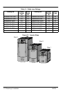
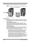
Power and Motor Connections
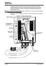
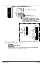
Figures 1-1and 1-2 show the minimum connections required at the power
connector.
Figure 1-1 Power Connections
10
9
8
7
6
5
4
3
2
1
M2/V
M3/W
L1
TH1A
TH1B
L2/N
RL1A
RL1B
M1/U
DBR
L3
DC+
Dynamic Brake Cable
Mains Supply
Cable
Motor Cable
Thermistor Cable
Wire Retainer
(Channel)
Control Signal Cable
L1, L2, L3, GND
Size 2 Shown
Use 2 Ground
Wires
Grounded
Cable Clamp
Use a cable tie
in this area for
control wires.
Motor
Connections
Dynamic Brake
Connections
AC Line
Connections
TH1A and TH1B must
be jumpered if
thermistor is not used