


Receiving & Installation 3–7MN735
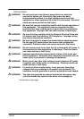
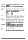
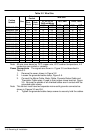
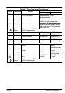
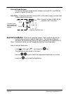
Table 3-3 Power Connection Descriptions
Range
Terminal Description Function
230V 1–Phase 460V 3–Phase
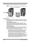
RLY1 Relay Output Normally open, programmable
contact for a relay output.
Contact closes when the programmed
condition (see Section 4) is true.
No voltage is present on this contact. 6
conditions are available.
TH1A Thermistor Connection to motor thermistor It is good practice to protect motors by using
thermistors. A typical resistance (up to a
reference temperature of 125_C) is 200Ω,
rising rapidly to 2000Ω above this temperature
TH1B Thermistor Connection to motor thermistor
r
i
s
i
ng rap
idl
y
t
o
2000Ω
a
b
ove
thi
s
t
empera
t
ure.
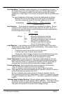
Connect devices in series between TH1A and
TH1B. Jumper TH1A and TH1B if temperature
sensors are not used.
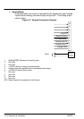
Reference
Terminal
Supply protective earth (PE). This terminal must be connected to a protective (earth)
ground for permanent ground.
L1 Power Input Single and three phase line
connection
220/240VAC±10%
with respect to L2/N.
380/460VAC±10%
with respect to L2, L3.
L2/N
L2
Power Input Single phase neutral (or L2 three
phase line connection)
220/240VAC±10%
with respect to L1.
380/460VAC±10%
with respect to L1, L3.
L3 Power Input Three phase line connection Not applicable 380/460VAC±10%
with respect to L1, L2.
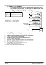
DC- No user connection
DC+ Dynamic Brake Connection to external brake
resistor
Not applicable Frame 2 (high volt
only) & 3.
See Internal Dynamic
Brake Switch" table
DBR Dynamic Brake Connection to external brake
resistor
Not applicable Frame 2 (high volt
only) & 3.
See Internal Dynamic
Brake Switch" table
M1/U
M2/V
M3/W
Power Outputs 3-phase supply connection for
motor
0 to 220/240VAC
0 to 240Hz
0 to 380/460VAC
0 to 240Hz
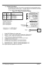
Reference
Terminal
Supply protective earth (PE). This terminal must be connected to a protective (earth)
ground for permanent ground.