


Receiving & Installation 3–13MN735
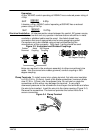
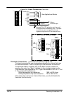
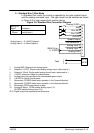
2 – Standard Run 3 Wire Mode
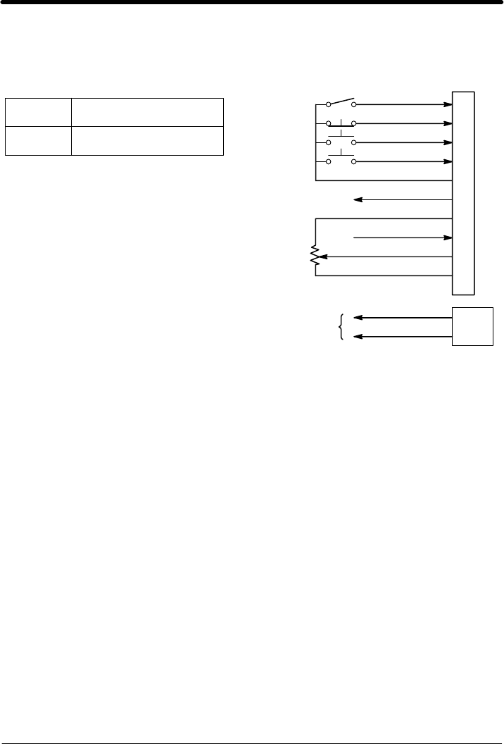
In Standard Run mode, the control is operated by the opto isolated inputs
and the analog command input. The opto inputs can be switches as shown
in Figure 3-8 or logic signals from another device.
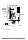
Figure 3-8 Standard Run Connection Diagram
8
9
10
Run REV
Stop
Analog IN SEL
Analog GND
Analog Input 1
Analog Input 2
Pot Reference
+24VDC
Run FWD
1
2
3
4
5
6
7
10KW Pot or
0-10VDC
Speed Output
RLY1A
RLY1B
Fault
Analog Input 1 = 0–10VDC Setpoint
Analog Input 2 = 4–20mA Setpoint
Analog IN
Select
Command
Open
Closed
Analog Input 1
Analog Input 2
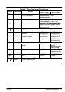
1 Analog GND. Reference for analog inputs.
2 Setpoint 0–10VDC. Single ended analog voltage input, referenced to 1.
3 Setpoint 4–20mA. Single ended analog current input, referenced to 1.
4 +10VDC reference voltage for potentiometer.
5 Analog output that represents the commanded speed output.
6 +24VDC for Optical Inputs power.
7 Momentary CLOSED starts motor operation in the Forward direction.
8 Momentary CLOSED starts motor operation in the Reverse direction.
9 Momentary OPEN motor decels to stop.
10 Analog IN Select. OPEN selects Analog Input 1 (2).
CLOSED selects Analog Input 2 (3).
RLY1 Digital output that represents the fault status.