


Start–Up and Operation 4–13MN735
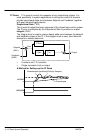
The gains should be set–up so that a critically damped response is
achieved for a step change in setpoint. An underdamped or oscillatory
system can be thought of as having too much gain, and an overdamped
system has too little.
To set up the P gain, set the I gain to zero. Apply a step change in setpoint
that is typical for the System, and observe the response. Increase the gain
and repeat the test until the system becomes oscillatory. At this point,
reduce the P gain until the oscillations disappear. This is the maximum
value of P gain achievable.
If a steady state error is present, i.e. the feedback never reaches the
setpoint value, the I gain needs to be increased. As before, increase the I
gain and apply the step change. Monitor the output. If the output becomes
oscillatory, reduce the P gain slightly. This should reduce the steady state
error. Increasing the I gain further may reduce the time to achieve zero
steady state error.
These values of P and I can now be adjusted to provide the exact response
required for this step change.
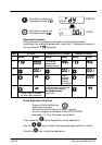
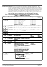
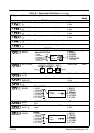
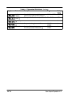
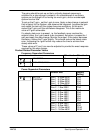
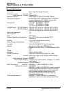
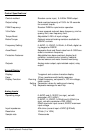
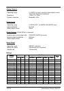
Product Related Parameter Values
Frequency Dependent Parameters
50Hz default 60Hz default
MAX SPEED 50 60
BASE FREQUENCY 50 60
Power Dependent Parameters
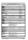
Inverter Size Factory
Setting
MOTOR
CURRENT
Size 1 : 0.25kw 230V
Size 1 : 0.37kw 230V
Size 1 : 0.55kw 230V
Size 1 : 0.75kw 230V
1.5A
2.2A
3.0A
4.0A
Size 2 : 1.1kw 230V
Size 2 : 1.5kw 230V
5.5A
7.0A
Size 2 : 1.5kw 460V
Size 2 : 2.0kw 460V
Size 2 : 2.5kw 460V
Size 2 : 3.5kw 460V
Size 2 : 4.5kw 460V
Size 2 : 5.5kw 460V
1.5A
2.0A
2.5A
3.5A
4.5A
5.5A
Size 3 : 6.8kw 460V
Size 3 : 9.0kw 460V
Size 3 : 12.0kw 460V
Size 3 : 16.0kw 460V
6.8A
9.0A
12.0A
16.0A