


4–6 Start–Up and Operation MN735
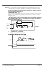
Parameter Definitions You can program the Inverter for specific applications. The
Inverter is supplied with pre–programmed applications that can be used as
starting points for application–specific programming. Programming is simply
selecting an application, changing some of the parameter values and finally
saving the changes. Each application configures the terminal wiring for a
differently. The Inverter retains the new settings during power–down. The
next time the inverter is powered up, the new settings will be used.
Note: Motor parameters are not changed when a new application is loaded.
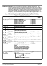
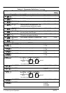
Table 4-1 Parameter Definitions
Display
Parameter Description Range Factory
Setting
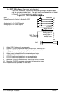
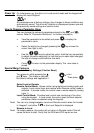
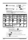
APPLICATION Selects the applicaton to be used
Application 1: Keypad mode
Application 2: Standard Run 3-Wire
Application 3: 3 Speed 2-Wire
Application 4: EPOT 3-Wire
Application 5: EPOT 2-Wire
Application 6: PID 2-Wire
0= Application 0
1= Application 1
2= Application 2
3= Application 3
4= Application 4
5= Application 5
6= Application 6
1
MAX SPEED The frequency at which the control will run
when maximum setpoint is applied
7.5 to 240.0Hz 60.0Hz
MIN SPEED The minimum frequency at which the control will
run.
-100.0 to 100.0% 0.0%
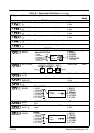
ACCEL TIME The time taken for the control output frequency
to ramp up from zero to MAX SPEED
0.0 to 3000.0s 5.0s
DECEL TIME The time taken for the control output frequency
to ramp down from MAX SPEED to zero
0.0 to 3000.0s 5.0s
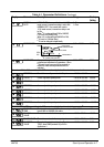
MOTOR
CURRENT
This parameter contains the motor nameplate
full-load line current
Product
code
dependent
Product
code
dependent
BASE
FREQUENCY
The output frequency at which maximum
voltage is reached. The default is Product Code
dependent.
25.0 to 240.0Hz 60.0Hz
JOG
SETPOINT
Speed the control will run at if the Jog input is
high
-100.0 to 100.0% 12.0%
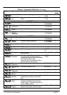
RUN STOP
MODE
RAMP : The motor speed is reduced to zero at
a rate set by DECEL TIME (
P
5). A 2 second
pulse is applied at end of ramp
COAST : The motor is allowed to freewheel to a
standstill
INJECTION : On a stop command, the motor
volts are rapidly reduced at constant frequency
to deflux the motor. A low frequency braking
current is then applied until the motor speed is
almost zero. This is followed by a timed DC
pulse to hold the motor shaft.
0=RAMP
1=COAST
2=INJECTION
0
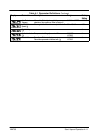
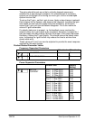
V/F SHAPE
LINEAR
FREQUENCY
= BASE FREQUENCY
00%
CONSTANT
POWER RANGE
OUTPUT VOLTS
f
B
f
B
QUADRATIC LAW
0=LINEAR
1=FAN
0