


1–4 Quick Start MN735
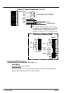
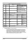
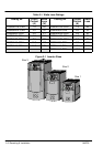
Table 1–2 Analog/Digital Signal Descriptions
Terminal
(SELV)
Signal Name Description Range
RL1A
User Relay
Volt-free contact - 4A maximum non-inductive
0-250VAC/24VDC
RL1B
U
ser
R
e
l
ay
V
o
l
t-
f
ree contact - 4
A
max
i
mum, non-
i
n
d
uct
i
ve
0
-
2
5
0VAC/2
4
VDC
10 DIN4/
DOUT2
Configurable I/O, Digital Input 4 or Digital Output 2. 0-24V source
open collector
9 DIN3 Digital Input 3. 0-24V source
open collector
8 DIN2 Digital Input 2. 0-24V source
open collector
7 DIN1 Digital Input 1. 0-24V source
open collector
6 +24V 24V ć 24V supply for digital I/O 50mA max
5 AOUT1 Analog Output ć 10mA maximum 0-10V
4 10VREF 10V reference (10mA maximum loading) 10V
3 AIN2 Analog Input 2 0-10V, 4-20mA
2 AIN1 Analog Input 1 - Setpoint. If unused, connect to 0VDC. 0-10V
1 0V 0V - Reference for Analog/Digital I/O
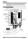
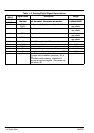
For single control installations, connect pin 1 (0V) to
PE.
For multiple control installations, connect the 0V
terminals of each control together. Then connect only
one control to PE.
0V