


1-6
Cisco ASA 5500-X Series Hardware Installation Guide
Chapter 1 Information about the ASA 5500-X
ASA Chassis Panels
Note Only SFP modules certified by Cisco are supported on the ASA.
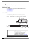
ASA Chassis Panels
This section describes the front and rear ASA panels, and it includes the following topics:
• Front Panel LEDs, page 1-6
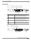
• Rear Panel LEDs, page 1-9
• Rear Panel Ports, page 1-11
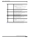
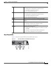
Front Panel LEDs
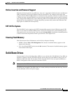
This section describes the front panel LEDs for the Cisco ASA 5500-X series chassis.
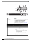
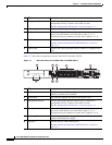
Figure 1-2 shows the front panel LEDs for the ASA 5512-X, ASA 5515-X, and ASA 5525-X models.
Figure 1-2 Front Panel LEDs for the Cisco ASA 5512-X, ASA 5515-X, and ASA 5525-X
LED Description
1 Power button A soft switch that turns the system on and off. Once depressed, the
button stays in the “on” position:
• On—The power symbol on the button illuminates.
• Off—The power symbol on the button is dark.
For information about the power state, see the “Power Supply
Considerations” section on page 2-4.
2 Hard disk release button Releases the hard disk from the device.
Cisco ASA 5515
Adapative Security Appliance
BOOT
ACTIVE
PS
ALARM
VPN
HD
282360
Cisco ASA 5515
Adapative Security Appliance
BOOT
ACTIVE
PS
ALARM
VPN
HD
1
2
5
8
7
6
3
4