


4-7
Cisco ASA 5500-X Series Hardware Installation Guide
Chapter 4 Maintenance and Upgrade Procedures for the ASA 5500-X
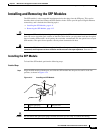
Installing an I/O Card
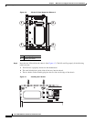
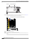
Step 10 Connect the blue connector end of the Regex ribbon cable to the motherboard, and close the green tab.
Step 11 Install the chassis cover, and replace the chassis in the rack.
Step 12 Install the power cable.
Step 13 For newer ASAs, the power turns on automatically when you plug in the power cable; do not press the
power button on the front panel.
For earlier ASAs, press the power button.
The LEDs will blink when traffic begins to pass through.
Installing an I/O Card in the Cisco ASA 5545-X and 5555-X Chassis
To replace an I/O card in an ASA 5545-X or 5555-X chassis, follow these steps.
Detailed Steps
Step 1 Power off the chassis, remove the power cable from the chassis, and remove the chassis from the rack.
Step 2 Locate a grounding strap, and fasten it to your wrist so that it contacts bare skin. Attach the other end to
the chassis. See the “Working in an ESD Environment” section on page 2-3 for more information.
Step 3 With your fingers, loosen the captive installation screw on the rear of the chassis.
Step 4 Remove the chassis cover by placing your hand on top of the chassis lid, pressing down firmly, and
pushing the cover toward the rear of the chassis.
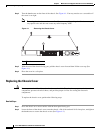
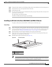
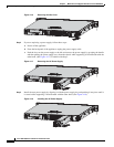
Step 5 Determine the location of the I/O card. (See Figure 4-8.)
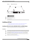
Figure 4-8 I/O Card Location
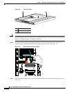
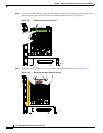
Note You must disconnect the blue Regex flexible circuit connector from the motherboard before
removing the I/O card from the chassis. The copper-colored Regex flexible circuit can break
during the I/O card removal or installation process, so handle it with care.
1 I/O Card holder
2 Power supply
282498
1
2