


4-13
Cisco ASA 5500-X Series Hardware Installation Guide
Chapter 4 Maintenance and Upgrade Procedures for the ASA 5500-X
Removing and Installing the Power Supply
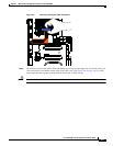
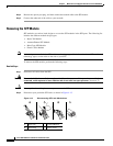
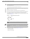
Step 3 Grasp the SFP on both sides, and remove it from the port.
Removing and Installing the Power Supply
• Removing and Installing the AC Power Supply, page 4-13
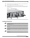
• Installing the DC Input Power, page 4-15
• Removing and Installing the DC Power Supply, page 4-19
Removing and Installing the AC Power Supply
Caution If you remove a power supply, replace it immediately to prevent disruption of service.
Caution If the appliance is subjected to environmental overheating, it shuts down and you must manually power
cycle it to turn it on again.
Warning
This unit has more than one power supply connection; all connections must be removed completely
to completely remove power from the unit.
Statement 102
Warning
This product relies on the building’s installation for short-circuit (overcurrent) protection. Ensure that
the protective device is rated not greater than: 120 VAC, 20A U.S. (240 VAC, 10A international).
Statement 1005
Note This procedure applies only to the appliances with a removable AC power supply (ASA 5545-X and ASA
5555-X). If only one power supply is installed, make sure that it is installed in slot 0 (left slot) and that
slot 1 (right slot) is covered with a slot cover.
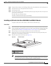
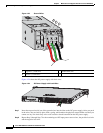
To remove and install the AC power supply, follow these steps:
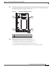
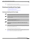
Step 1 If you are adding an additional power supply, from the back of the appliance, push the lever on the slot
cover to the left to release it, grasp the handle of the slot cover and pull it away from the chassis. (See
Figure 4-16.) Save the slot cover for future use. Continue with Step 3.