


4-16
Cisco ASA 5500-X Series Hardware Installation Guide
Chapter 4 Maintenance and Upgrade Procedures for the ASA 5500-X
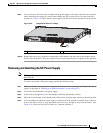
Removing and Installing the Power Supply
Warning
This product relies on the building’s installation for short-circuit (overcurrent) protection. Ensure that
the protective device is rated not greater than: 80 VAC, 20A.
Statement 1005
The DC power supply is shipped installed in the chassis, either one or two power supplies depending on
which configuration you ordered. You must connect the power supply wires. This section describes how
to install the DC power supply ground leads and input power leads to the appliance DC input power
supply. Before you begin, read these important notices:
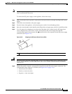
• The color coding of the DC input power supply leads depends on the color coding of the DC power
source at your site. Typically, green or green/yellow is used for ground (GND), black is used for –48
V on the negative (–) terminal, and red is used for RTN on the positive (+) terminal. Ensure that the
lead color coding you choose for the DC input power supply matches the lead color coding used at
the DC power source.
• Make sure that the chassis ground is connected on the chassis before you begin installing the DC
power supply. See “Working in an ESD Environment” section on page 2-3 for more information.
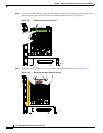
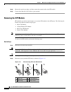
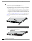
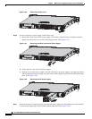
Figure 4-20 shows the back panel of the ASA 5512-X, ASA 5515-X, and ASA 5525-X with the DC
power supply.
Figure 4-20 ASA 5512-X, ASA 5515-X, and ASA 5525-X Back Panel
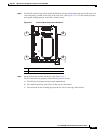
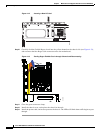
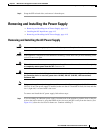
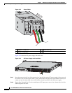
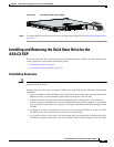
Figure 4-21 shows the back panel of the ASA 5545-X and ASA 5555-X with two DC power supplies.
Figure 4-21 ASA 5545-X and ASA 5555-X Back Panel
1 Fixed fan 2 Fixed DC power supply
333226
1 2
333059