


4-2
Cisco ASA 5500-X Series Hardware Installation Guide
Chapter 4 Maintenance and Upgrade Procedures for the ASA 5500-X
Removing and Replacing the Chassis Cover
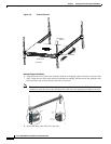
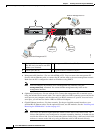
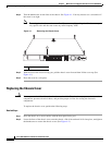
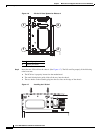
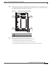
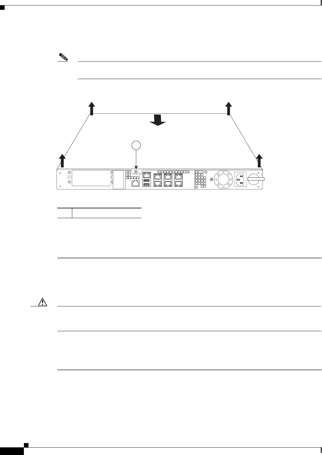
Step 2 Turn the thumbscrew on the front of the chassis. See Figure 4-1. You may need to use a screwdriver if
the screw is too tight.
Note Removing the chassis cover does not affect Cisco warranty. Upgrading the ASA does not require
any special tools and does not create any radio frequency leaks.
Figure 4-1 Removing the Chassis Cover
Step 3 With the rear of the chassis facing you, pull the chassis cover forward then lift the cover up. (See
Figure 4-1.)
Step 4 Place the cover in a safe place.
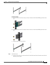
Replacing the Chassis Cover
Caution Do not operate the ASA without the chassis cover installed. The chassis cover protects the internal
components, prevents electrical shorts, and provides proper air-flow for cooling the electronic
components.
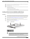
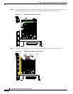
To replace the chassis cover, perform the following steps.
Detailed Steps
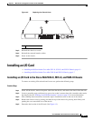
Step 1 Place the chassis on a secure surface with the front panel facing you.
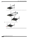
Step 2 Lower the front of the chassis cover onto the chassis, slide it forward until it fits into place, and tighten
the thumbscrew to secure the chassis cover. (See Figure 4-2.)
1 Thumbscrew
282506
1