


1-13
Cisco ASA 5500-X Series Hardware Installation Guide
Chapter 1 Information about the ASA 5500-X
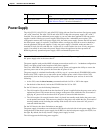
Power Supply
Power Supply
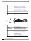
The ASA 5512-X, ASA 5515-X, and ASA 5525-X ship with one fixed fan and one fixed power supply
(AC or DC) installed. The ASA 5545-X and ASA 5555-X ship with one power supply (AC or DC)
installed. You can add an additional power supply or you can order these appliances with two power
supplies installed. Having two power supplies installed provides a redundant power option. This
configuration ensures that if one power supply fails, the other power supply assumes the full load until
the failed power supply is replaced. To maintain airflow, an empty bay must be covered or both bays
must be populated with power supplies. If only one power supply is installed, make sure that it is
installed in slot 0 (left slot) and that slot 1 (right slot) is covered with a slot cover. If only one power
supply is installed, do not remove the power supply unless the appliance has been powered off.
Removing the only operational power supply causes an immediate power loss.
Note The ASA 5545-X and ASA 5555-X can support two AC or two DC power supplies. Do not mix AC and
DC power supply units in the same chassis.
The power supplies each provide 400 W of output power and are used in a 1 + 1 redundant configuration.
There is no input switch on the faceplate of the power supplies.
The Cisco ASA 5500-X series hardware operates on AC power and supports the ability to restore the
previous power state of the system in the event that AC power is lost.
The power supply is switched from Standby to ON by way of a system chassis STANDBY/ON switch.
Earlier ASAs (V01) require you to turn on the power with the power switch. Newer ASAs (V02)
automatically turn on when you plug in the power cable. To determine your version, do one of the
following:
• At the CLI, enter the show inventory command and look for V01 or V02 in the output.
• On the back of the chassis, look at the VID PID label for V01 or V02.
For the V01 chassis, see the following limitations:
• The ASA requires 50 seconds from the time that AC power is applied before the power state can be
updated and stored. This means that any changes to the power state within the first 50 seconds of
applying AC power will not be observed if AC power is removed within that time.
• The ASA requires 10 seconds from the time it is placed into standby mode before the power state
can be updated and stored. This means any changes to the power state within the first 10 seconds of
entering standby mode (including the standby mode itself) will not be observed if AC power is
removed within that time.
For the V02 chassis, the above limitations to not apply.
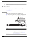
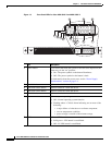
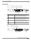
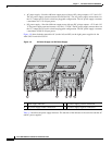
The power supply slot numbers are on the back of the chassis to the left side of each power supply. When
facing the back of the chassis, power supply slot 0 (PS0) is to the left and power supply slot 1(PS1) is to
the right. By default, the factory installs a single power supply in slot 0.
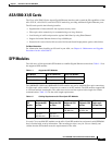
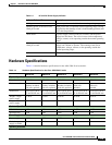
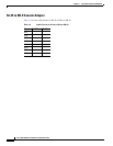
The ASA supports the following power supplies:
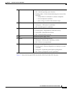
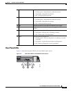
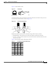
7 Console port Indicates the console port that directly connects a computer to the
ASA.
8 Rear panel LEDs Shows the rear panel LEDs. (See the “Rear Panel LEDs for ASA
5500-X Series Chassis” for more information.)