


4-3
Cisco ASA 5500-X Series Hardware Installation Guide
Chapter 4 Maintenance and Upgrade Procedures for the ASA 5500-X
Installing an I/O Card
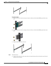
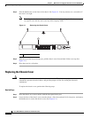
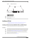
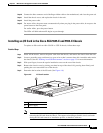
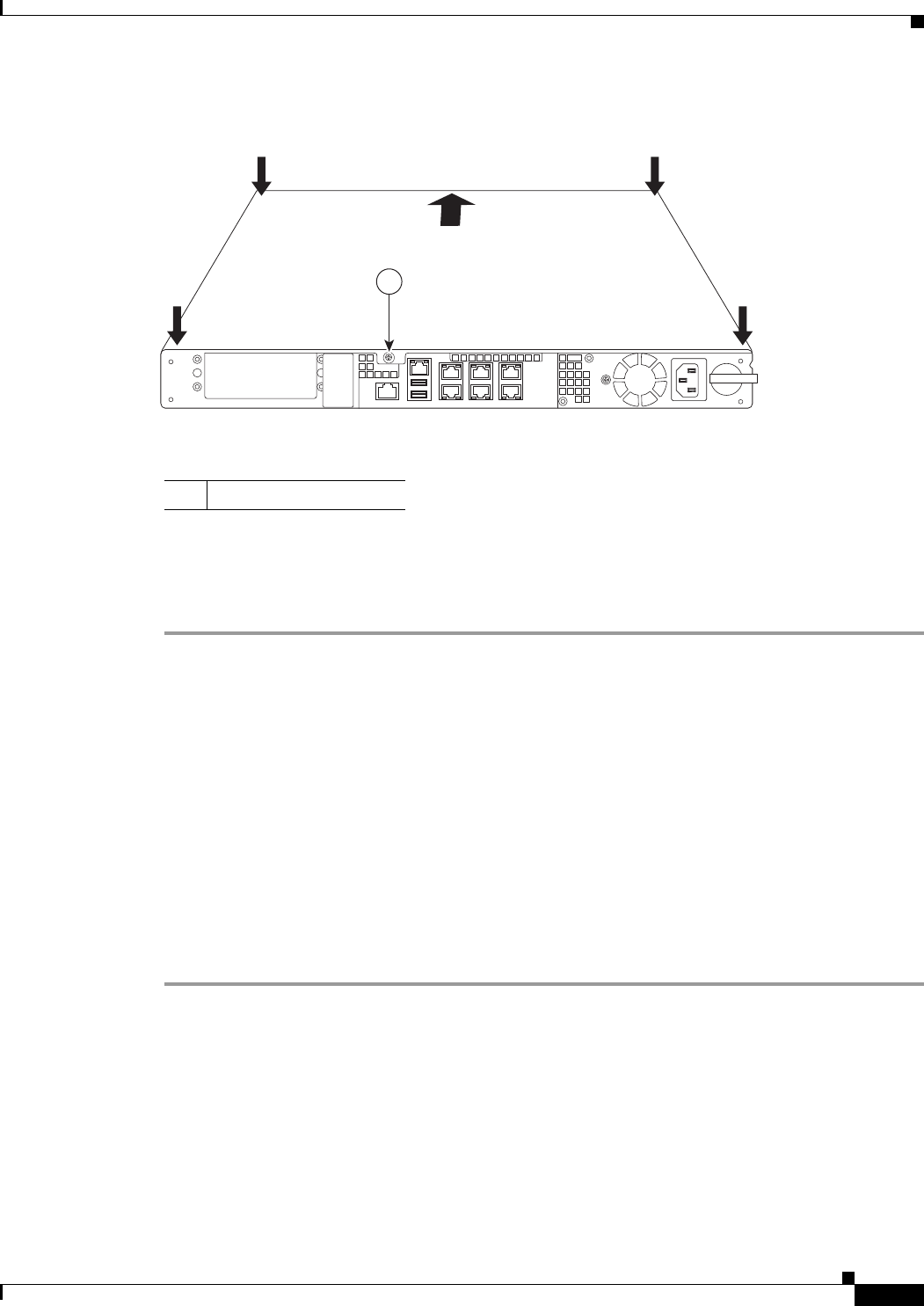
Figure 4-2 Replacing the Chassis Cover
Step 3
Reinstall the chassis on a rack.
Step 4 Reinstall the network interface cables.
Step 5 Power on the chassis.
Installing an I/O Card
• Installing an I/O Card in the Cisco ASA 5512-X, 5515-X, and 5525-X Chassis, page 4-3
• Installing an I/O Card in the Cisco ASA 5545-X and 5555-X Chassis, page 4-7
Installing an I/O Card in the Cisco ASA 5512-X, 5515-X, and 5525-X Chassis
To remove an existing I/O card and install a new one, perform the following steps.
Detailed Steps
Step 1 Power off the chassis, remove the power cable from the chassis, and remove the chassis from the rack.
Step 2 Locate a grounding strap, and fasten it to your wrist so that it contacts bare skin. Attach the other end to
the chassis. See the “Working in an ESD Environment” section on page 2-3 for more information.
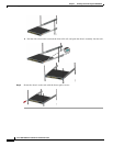
Step 3 With a Phillips head screwdriver, loosen the captive installation screw on the rear of the chassis
Step 4 Remove the chassis cover by placing your hand on top of the chassis lid, pressing down firmly, and
pushing the cover toward the rear of the chassis.
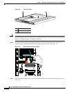
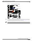
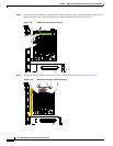
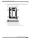
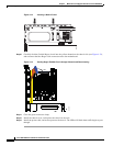
Step 5 Determine the location of the I/O card. (See Figure 4-3.)
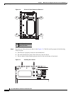
1 Thumbscrew
282616
1