


4-15
Cisco ASA 5500-X Series Hardware Installation Guide
Chapter 4 Maintenance and Upgrade Procedures for the ASA 5500-X
Removing and Installing the Power Supply
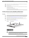
Step 4 Connect the power cable. If you are installing two power supplies for a redundant configuration, plug
each one into a power source (we recommend a UPS).
Step 5 Power on the appliance if you powered it off to replace the only power supply.
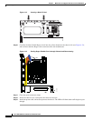
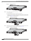
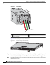
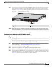
Step 6 Check the PS0 and PS1 indicators on the front panel to make sure they are green. On the back panel of
the appliance, make sure the power supply indicator on the bottom of each installed power supply is
green. (See Figure 4-19.)
Figure 4-19 Back Power Supply Indicators
Installing the DC Input Power
Warning
The covers are an integral part of the safety design of the product. Do not operate the unit without the
covers installed.
Statement 1077
Warning
When you install the unit, the ground connection must always be made first and disconnected last.
Statement 1046
Warning
Before performing any of the following procedures, ensure that power is removed from the DC circuit.
Statement 1003
Warning
Only trained and qualified personnel should be allowed to install, replace, or service this equipment.
Statement 1030
331087
PS1
PS0