


1-9
Cisco ASA 5500-X Series Hardware Installation Guide
Chapter 1 Information about the ASA 5500-X
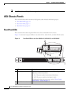
ASA Chassis Panels
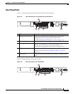
Rear Panel LEDs
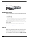
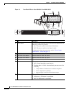
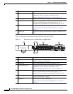
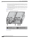
Figure 1-4 shows the rear panel LEDs for the ASA 5500-X series chassis.
Figure 1-4 Rear Panel LEDs for ASA 5500-X Series Chassis
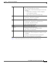
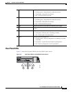
8 HD1 Indicates Hard Disk Drive 1 status:
• Flashing green—Proportioned to read/write activity.
• Solid amber—Hard disk drive failure.
• Off—No hard disk drive present.
9 HD0 Indicates Hard Disk Drive 0 status:
• Flashing green—Proportioned to read/write activity.
• Solid amber—Hard disk drive failure.
• Off—No hard disk drive present.
10 PS1 Indicates the status of the optional redundant power supply.
11 PS0 Indicates the status of the primary power supply that ships with the
product.
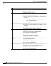
12 Active Indicates the status of the failover pair:
• Solid green—Failover pair is operating normally.
• Off—Failover pair is not operational.
13 Boot Indicates power-up diagnostics:
• Flashing green—Power-up diagnostics are running, or system
is booting.
• Solid green—System has passed power-up diagnostics.
• Off—Power-up diagnostics are not operational.
332118
2 64
1 753