


4-19
Cisco ASA 5500-X Series Hardware Installation Guide
Chapter 4 Maintenance and Upgrade Procedures for the ASA 5500-X
Removing and Installing the Power Supply
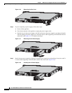
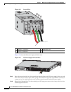
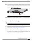
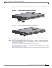
Step 9 Use a tie wrap to secure the wires coming from the power supply to the rack so that the wires cannot be
pulled from the power supply by casual contact. Make sure the tie wrap allows for some slack in the
ground wire. Figure 4-25 shows the DC power supply with the wires inserted and the tie wrap secured.
Figure 4-25 Complete DC Secure Tie Wrap
Step 10
Remove the tape (if any) from the circuit breaker switch handle, and move the circuit breaker switch
handle to the On position. The power supply indicators light up when power is supplied to the appliance.
Removing and Installing the DC Power Supply
Note This procedure applies only to the appliances with a removable DC power supply (ASA 5545-X and
ASA 5555-X).
To remove and install a DC power supply, perform the following steps:
Step 1 Make sure that the chassis ground is connected on the chassis before you begin installing the DC power
supply, as described in “Working in an ESD Environment” section on page 2-3.
Step 2 Turn off the circuit breaker to the power supply.
Step 3 At the back of the appliance, place the Standby switch into the Standby position.
Step 4 Move the circuit-breaker switch handle to the Off position, and apply tape to hold it in the Off position.
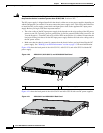
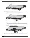
Step 5 If you are adding an additional power supply, from the back of the appliance, push the lever on the slot
cover to the left to release it, grasp the handle of the slot cover, and pull it away from the chassis. (See
Figure 4-26.) Save the slot cover for future use. Continue with Step 7.
1 Lead wires secured with a tie wrap
333061
1