3-13
Cisco ASA 5500-X Series Hardware Installation Guide
Chapter 3 Installing and Connecting the ASA 5500-X
Connecting Cables, Turning on Power, and Verifying Connectivity
Connecting Cables, Turning on Power, and Verifying
Connectivity
This section describes how to connect the cables to the chassis and how to turn on the power.
Guidelines
Warning
Only trained and qualified personnel should install, replace, or service this equipment
.
Statement 49
Caution Be sure to read the safety warnings in the Regulatory Compliance and Safety information document for
the ASA 5500-X and follow proper safety procedures when performing all tasks in this guide. See the
RCSI at http://www.cisco.com/en/US/docs/security/asa/hw/regulatory/compliance/asa5500x_rcsi.html.
The Cisco ASA 5500-X series hardware operates on AC power and supports the ability to restore the
previous power state of the system in the event that AC power is lost.
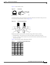
Earlier ASAs (V01) require you to turn on the power with the power switch. Newer ASAs (V02)
automatically turn on when you plug in the power cable. To determine your version, do one of the
following:
• At the CLI, enter the show inventory command and look for V01 or V02 in the output.
• On the back of the chassis, look at the VID PID label for V01 or V02.
For the V01 chassis, see the following limitations:
• The ASA requires 50 seconds from the time that AC power is applied before the power state can be
updated and stored. This means that any changes to the power state within the first 50 seconds of
applying AC power will not be observed if AC power is removed within that time.
• The ASA requires 10 seconds from the time it is placed into standby mode before the power state
can be updated and stored. This means any changes to the power state within the first 10 seconds of
entering standby mode (including the standby mode itself) will not be observed if AC power is
removed within that time.
For the V02 chassis, the above limitations to not apply.
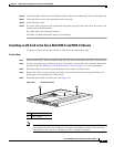
Detailed Steps
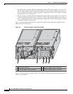
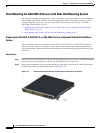
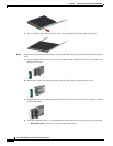
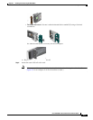
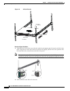
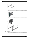
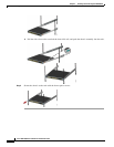
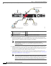
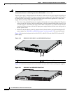
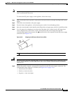
Step 1 Place the chassis on a flat, stable surface, or in a rack (if you are rack-mounting it.)
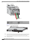
Step 2 Connect the interface cables.