


3-5
Cisco ASA 5500-X Series Hardware Installation Guide
Chapter 3 Installing and Connecting the ASA 5500-X
Rack Mounting the Chassis
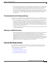
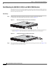
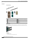
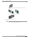
Step 3 Install a die-cast bracket to either side of the chassis by aligning and inserting the tab at the end of the
bracket into the hole on the chassis and then hinging it into position so that the bracket is flush with the
front face plate (bezel) of the chassis. Secure each bracket to the chassis with three screws.
(See Figure 3-6.)
Figure 3-6 Install Die-Cast Brackets with Three Screws
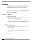
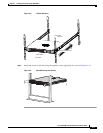
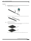
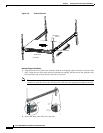
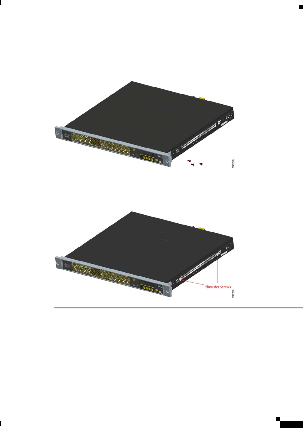
Step 4 Install two shoulder screws into the threaded hole locations on either side of the chassis (see Figure 3-7
for one side), and ensure that they are tight.
Figure 3-7 Install Two Shoulder Screws on Either Side of the Chassis
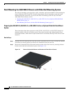
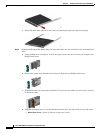
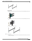
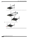
Rack Mounting the Chassis with the Slide Rail Mounting System
This section describes how to rack mount the chassis using the slide rail mounting system.
Although slide rail mounting is preferred, in the case of two-rail racks where the slide rails will not fit,
you can use the rack mounting brackets. You must order them separately (ASA-BRACKETS=). Note
that there will be a slight bend in the brackets when you attach them. For the procedure for attaching the
brackets to the front or back of the chassis, see the “Rack Mounting the ASA 5512-X, 5515-X, and
5525-X With Brackets” section on page 3-2.