


1-8
Cisco ASA 5500-X Series Hardware Installation Guide
Chapter 1 Information about the ASA 5500-X
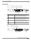
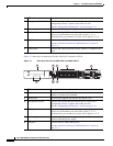
ASA Chassis Panels
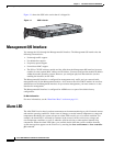
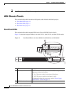
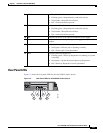
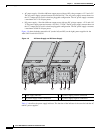
Figure 1-3 Front Panel LEDs for Cisco ASA 5545-X and ASA 5555-X
LED Description
1 Power button A soft switch that turns the system on and off. Once depressed, the
button stays in the “on” position:
• On—The power symbol on the button illuminates.
• Off—The power symbol on the button is dark.
For information about the power state, see the “Power Supply
Considerations” section on page 2-4.
2 Hard disk slot Indicates the slot for hard disk 1.
3 Hard disk release button Releases hard disk 1 from the device.
4 Hard disk release button Releases hard disk 0 from the device.
5 Hard disk slot Indicates the slot for hard disk 0.
6 Alarm Indicates system operating status:
• Off—Normal operating system function
• Flashing amber—Critical Alarm indicating one or more of the
following:
–
a major failure of a hardware or software component.
–
an over-temperature condition.
–
power voltage is outside of the tolerance range.
7 VPN Indicates VPN tunnel status:
• Solid green—VPN tunnel is established.
• Off—No VPN tunnel is established.
Cisco ASA 5545
Adapative Security Appliance
BOOT
ACTIVE
PS1
PS0
ALARM
VPN
HD1
HD0
1
0
Cisco ASA 5545
Adapative Security Appliance
BOOT
ACTIVE
PS1
PS0
ALARM
VPN
HD1
HD0
1
0
282359
1
3
4
9
2
13
12
11
10
5
6
7
8