


CHAPTER
3-1
Cisco ASA 5500-X Series Hardware Installation Guide
3
Installing and Connecting the ASA 5500-X
This chapter describes how to rack-mount the ASA and connect the interface cables, and it includes the
following sections:
• Rack Mounting the Chassis, page 3-1
• Connecting Cables, Turning on Power, and Verifying Connectivity, page 3-13
Rack Mounting the Chassis
• Rack Mounting Guidelines, page 3-1
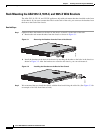
• Rack Mounting the ASA 5512-X, 5515-X, and 5525-X With Brackets, page 3-2
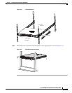
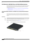
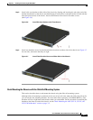
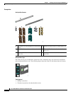
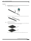
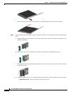
• Rack Mounting the ASA 5500-X Chassis with Slide Rail Mounting System, page 3-4
Rack Mounting Guidelines
Warning
To prevent bodily injury when mounting or servicing this unit in a rack, you must take special
precautions to ensure that the system remains stable. The following guidelines are provided to ensure
your safety:
This unit should be mounted at the bottom of the rack if it is the only unit in the rack.When mounting
this unit in a partially filled rack, load the rack from the bottom to the top with the heaviest component at the bottom
of the rack.If the rack is provided with stabilizing devices, install the stabilizers before mounting or servicing the unit
in the rack.
Statement 1006
The following information can help plan equipment rack installation:
• Allow clearance around the rack for maintenance.
• If the rack contains stabilizing devices, install the stabilizers prior to mounting or servicing the unit
in the rack.
• When mounting a device in an enclosed rack, ensure adequate ventilation. Do not overcrowd an
enclosed rack.
Make sure that the rack is not congested, because each unit generates heat.
• When mounting a device in an open rack, make sure that the rack frame does not block the intake
or exhaust ports.
• If the rack contains only one unit, mount the unit at the bottom of the rack.
• If the rack is partially filled, load the rack from the bottom to the top, with the heaviest component
at the bottom of the rack.