


3-14
Cisco ASA 5500-X Series Hardware Installation Guide
Chapter 3 Installing and Connecting the ASA 5500-X
Connecting Cables, Turning on Power, and Verifying Connectivity
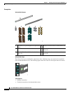
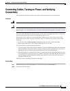
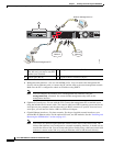
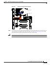
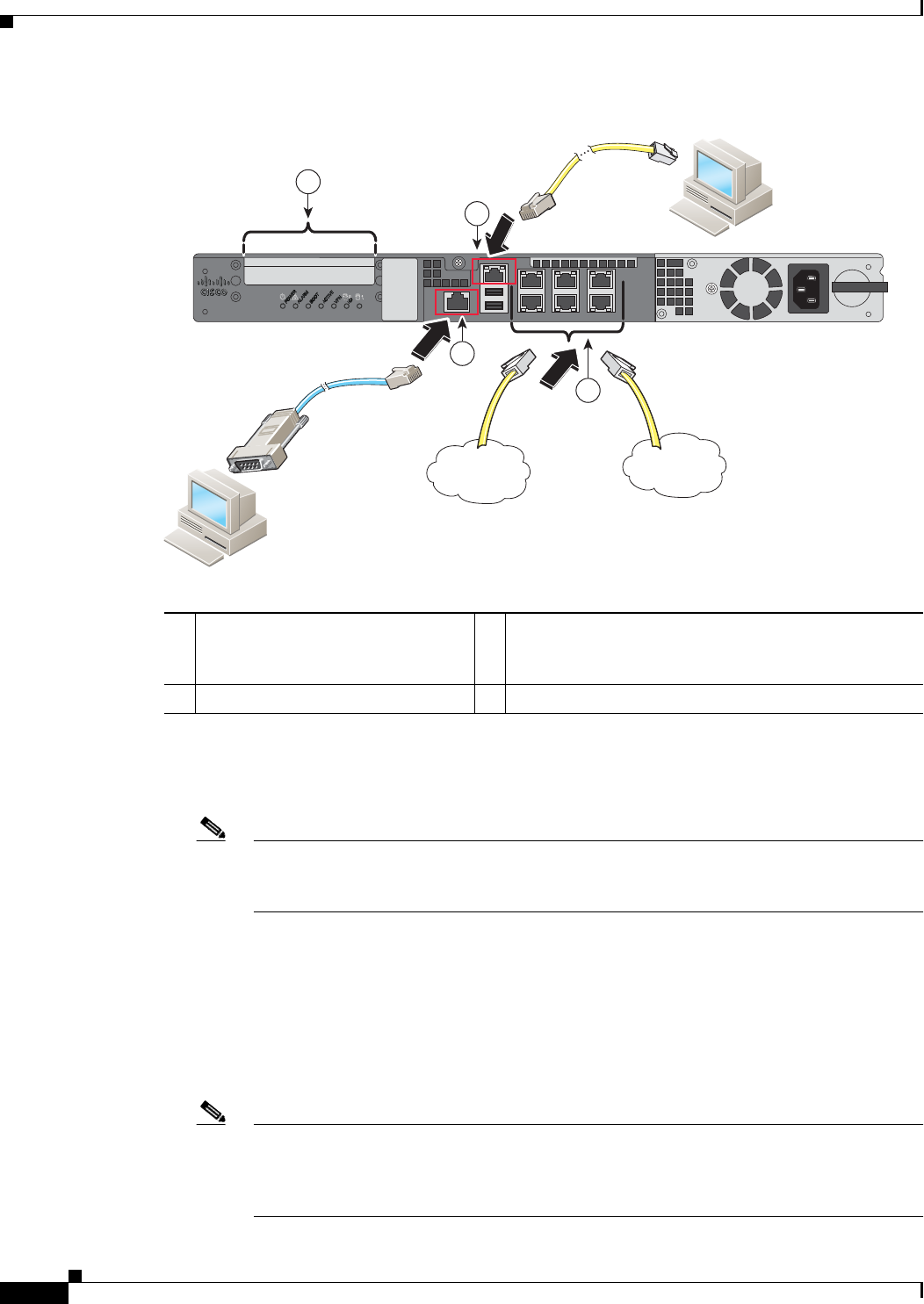
a. Management 0/0 interface—For use with ASDM or CLI. You can connect the management PC
directly with an Ethernet cable, or connect the PC and the ASA to the same management network.
Make sure the PC is configured to obtain an IP address using DHCP.
Note You can configure any interface to be a management-only interface using the
management-only command. You cannot disable management-only mode on the
management interface.
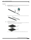
b. (Optional) Console port—For use with the CLI. Connect the management PC or terminal server
using the included serial console cable. The console cable has a DB-9 connector on one end for the
serial port on your computer, and the other end is an RJ-45 connector. If your PC does not have a
serial port, you will need to obtain a DB-9-to-USB serial adapter.
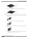
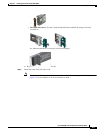
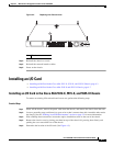
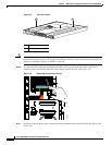
c. Gigabit Ethernet interfaces—For data networks. For the pre-installed network interfaces, use a
standard RJ-45 Ethernet cable. For the optional I/O card, use SFP modules. See the “Installing and
Removing the SFP Modules” section on page 4-11.
Note You can use any unused Gigabit Ethernet interface on the ASA as the failover link. The
failover link interface is not configured as a normal networking interface; it should only be
used for the failover link. You can connect the failover link by using a dedicated switch with
no hosts or routers on the link or by using an Ethernet cable to link the units directly.
1 (Optional) I/O Card. If you have a
fiber I/O card, you need to use SFP
modules (not included).
2 Management 0/0 interface (RJ-45)
3 Console port (RJ-45) 4
Gigabit Ethernet interfaces (RJ-45)
370600
Network Management PC
Console Management PC
Unsecured
Network
Secured
Network
2
3
4
1