


4-17
Cisco ASA 5500-X Series Hardware Installation Guide
Chapter 4 Maintenance and Upgrade Procedures for the ASA 5500-X
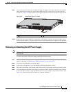
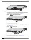
Removing and Installing the Power Supply
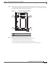
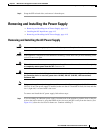
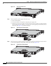
Note If only one power supply is installed, make sure that it is installed in slot 0 (left slot) and that slot 1 (right
slot) is covered with a slot cover.
To connect the DC power supply on the appliance, follow these steps:
Step 1 Make sure that the chassis ground is connected on the chassis before you begin installing the DC power
supply.
Step 2 Turn off the circuit breaker to the power supply.
Step 3 From the front of the appliance, verify that the power switch is in the Standby position.
Step 4 Move the circuit-breaker switch handle to the Off position, and apply tape to hold it in the Off position.
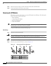
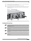
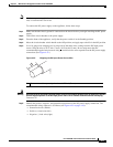
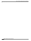
Step 5 Use a 10 gauge wire-stripping tool to strip each of the three wires coming from the DC input power
source. Strip the wires to 0.27 inch (7 mm) +
0.02 inch (0.5 mm). Do not strip more than the
recommended length of wire because doing so could leave the wire exposed from the DC power supply
connection. (See Figure 4-22.)
Figure 4-22 Stripping the DC Input Power Source Wire
Warning
An exposed wire lead from a DC input power source can conduct harmful levels of electricity. Be sure
that no exposed portion of the DC input power source wire extends from the terminal block plug.
Statement 122
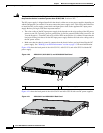
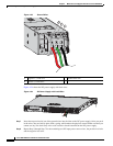
Step 6 Identify the positive, negative, and ground feed positions for the DC power supply connection. The
recommended wiring sequence is as follows (see Figure 4-23 on page 4-18):
• Ground lead wire (middle)
• Positive (+) lead wire (left)
• Negative (–) lead wire (right)
1 We recommend that you strip the wire to 0.27 inch (7 mm).
333062
1