


1-12
Cisco ASA 5500-X Series Hardware Installation Guide
Chapter 1 Information about the ASA 5500-X
ASA Chassis Panels
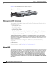
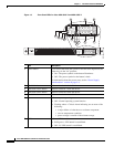
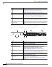
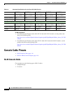
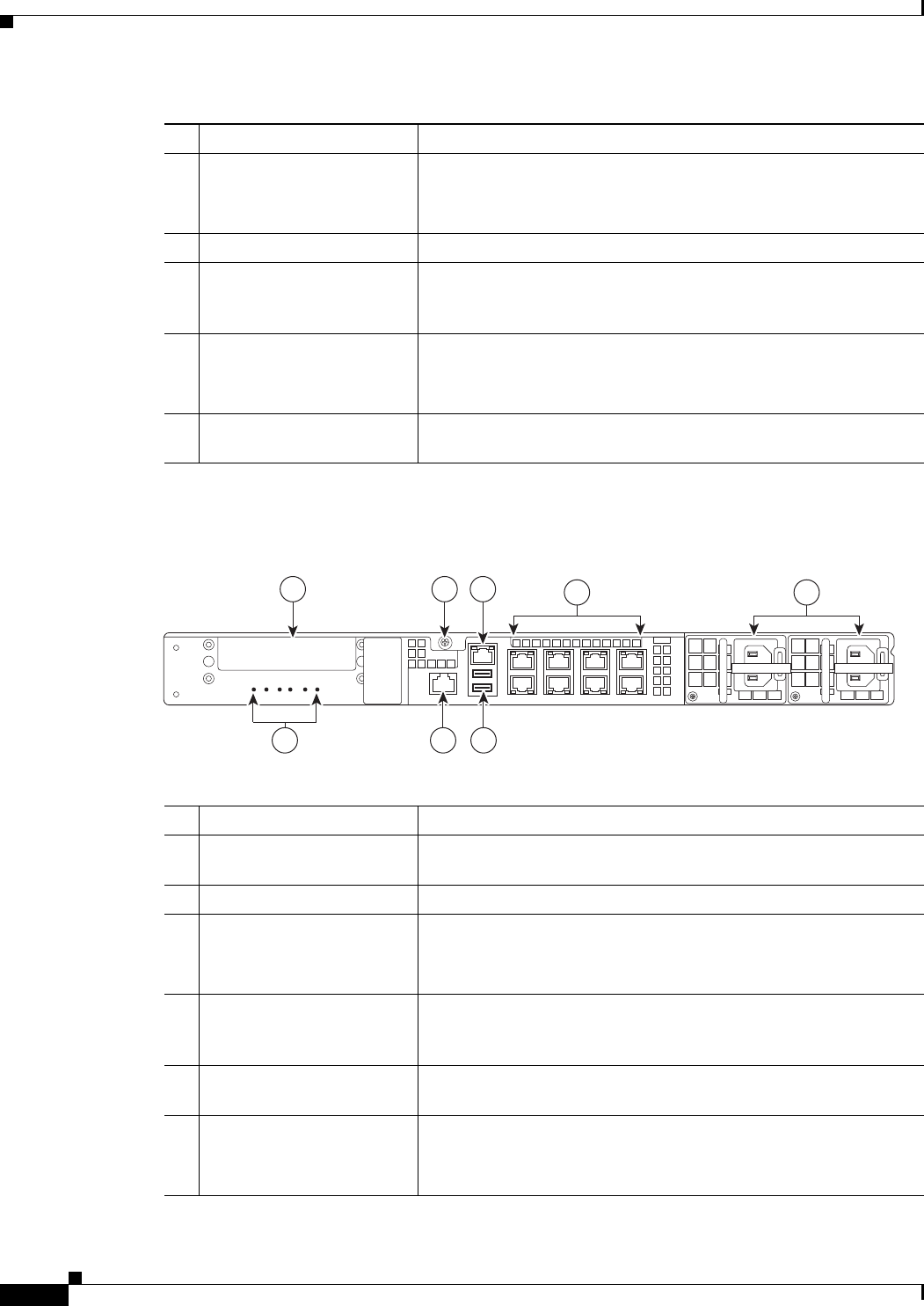
Figure 1-7 shows the rear panel ports for the ASA 5545-X and ASA 5555-X.
Figure 1-7 Rear Panel Ports for the ASA 5545-X and ASA 5555-X
LED Description
1 Management 0/0 interface Indicates the Gigabit Ethernet interface that is restricted to
management use only. Connect with an RJ-45 cable.
(See the “Management 0/0 Interface” section on page 1-4.)
2 Power supply Indicates the chassis power supply.
3 RJ-45 ports Indicates the Gigabit Ethernet customer data interfaces.
The top row port numbers are (from left to right) 7, 5, 3, 1.
The bottom row port numbers are (from left to right) 6, 4, 2, 0.
4 USB Ports Indicates the two USB standard ports.
(See the “Internal and External USB Flash Drives” section on
page 1-2.)
5 Console port Indicates the console port that directly connects a computer to the
ASA.
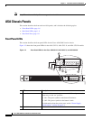
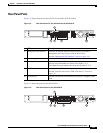
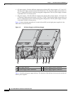
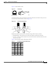
LED Description
1 I/O slot Slot for the optional I/O Card. If you have a fiber I/O card, use SFP
modules to connect (not included).
2 Thumbscrew The screw that tightens and loosens the chassis cover.
3 Management 0/0 port Indicates the Gigabit Ethernet interface that is restricted to
management use only. Connect with an RJ-45 cable.
(See the “Management 0/0 Interface” section on page 1-4.)
4 RJ-45 ports Indicates the Gigabit Ethernet customer data interfaces.
The top row port numbers are (from left to right) 7, 5, 3, 1.
The bottom row port numbers are (from left to right) 6, 4, 2, 0.
5 Power supplies Slots for the primary power supply that ships with the device and the
optional redundant power supply.
6 USB ports Indicates the two USB standard ports.
(See the “Internal and External USB Flash Drives” section on
page 1-2.)
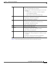
POWER
ALARMv
BOOT
ACTIVE
VPN
HD
282362
21 3
678
4 5