


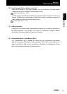
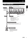

Section 1 FEATURES
Section 1
Basic Configuration
1-7
ZS-MDC
User’s Manual
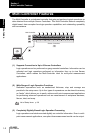
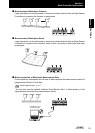
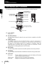
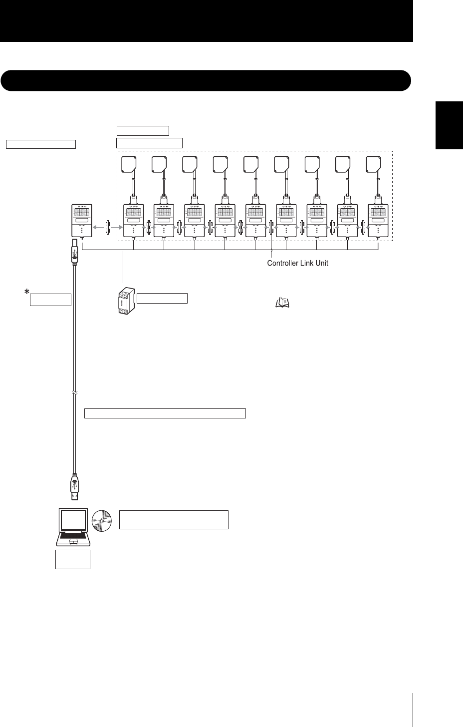
Basic Configuration
The figure below shows the Basic Configuration of the ZS Series.
This section detects the sensing object and processes measurement.
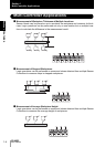
Up to 9 Sensor Controllers can be gang-mounted.
For details, refer to the User's Manual for the Sensor Controller.
Sensor Heads
Sensor Controllers
ZS-MDC11/MDC41
The Multi-Controller calculates
the measurement information
of gang-mounted Sensor
Controllers, and outputs
the calculation results.
Multi-Controller
Personal
computer
ZS-XCN
This unit is for gang-mounting controllers.
ZS-XRS2
RS-232C cable for personal computer connection
DC24V ( 10%)
Recommended parts
(1) When 1 Sensor Controller is connected
S82K-01524 (DC24V, 0.6 A)
(2) When 2 to 3 Sensor Controllers are connected
S82K-05024 (DC24V, 2.1 A)
(3) When 4 to 10 Sensor Controllers are connected
Prepare the required number of (1) and (2)
power supplies above.
Power Supply
USB cable
(1m)
This is used for communicating with a personal computer without a USB port.
(SmartMonitor Zero cannot be used on the RS-232C interface.
Communication using CompoWay/F or non-procedural protocol is possible.)
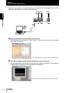
SmartMonitor Zero
(option software, sold separately)
ZS-SW11E
allows you to operate the Multi-Controller and
connected Sensor Controller, monitor or log
measured values from a personal computer.
In this manual, the software is referred to as
"SmartMonitor Zero".
+
-
p.2-5